Author: Pralay Bhunia

  • PNP Transistor – Construction, Working & Uses

    PNP Transistor – Construction, Working & Uses

    Transistors are the heart of modern electronics, enabling everything from simple amplifiers to complex computing systems. Among the different types, the PNP transistor plays a vital role in controlling current flow, signal amplification, and switching operations. As a part of the Bipolar Junction Transistor (BJT) family, the PNP transistor is known for using holes as majority charge carriers, making it essential in circuits where negative polarity control is required.

    What is a PNP Transistor?

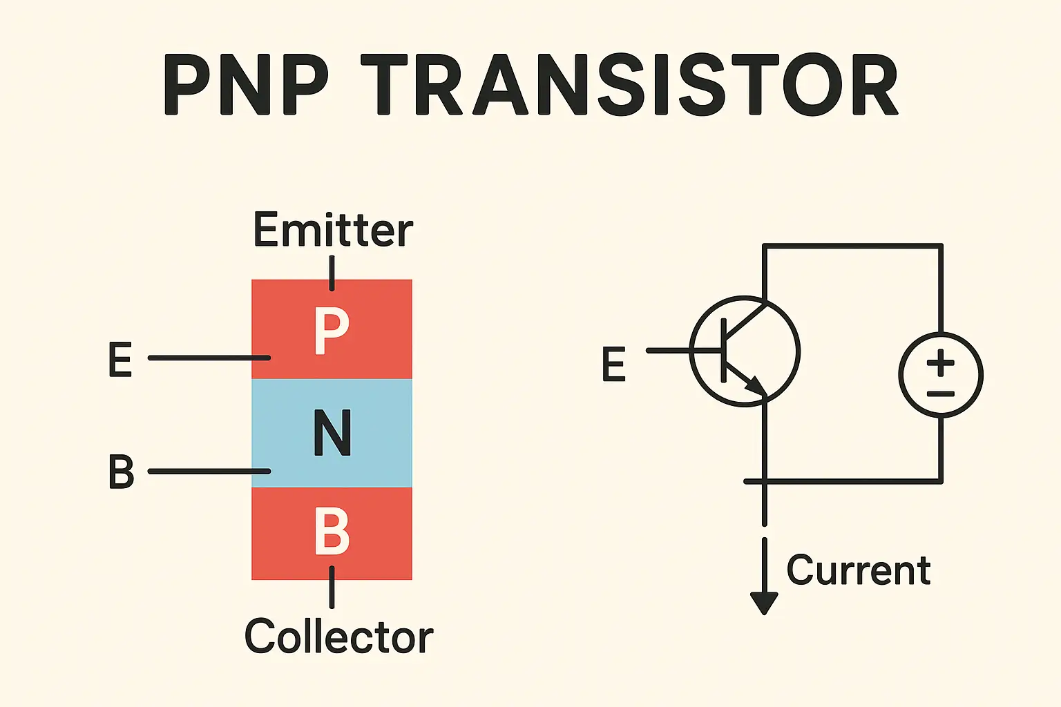
    A PNP transistor is a bipolar junction transistor made up of two p-type semiconductors separated by a thin n-type layer. It consists of three regions: the Emitter (E), Base (B), and Collector (C).

    The PNP transistor operates by controlling the flow of charge carriers (holes) from the Emitter to the Collector. Unlike an NPN transistor, which uses electrons as majority carriers, the PNP transistor depends on the movement of holes, making its operation opposite in polarity.

    In simple terms, when a small negative current flows into the base, it allows a larger current to flow from the emitter to the collector. This characteristic makes PNP transistors ideal for high-side switching and positive voltage control applications.

    Construction of PNP Transistor

    The PNP transistor is constructed by sandwiching a thin n-type base between two p-type layers.

    • The Emitter region is heavily doped to supply a large number of holes.
    • The Base region is thin and lightly doped to allow easy carrier movement.
    • The Collector region is moderately doped and larger in size to collect carriers efficiently.

    Three terminals extend from these regions:

    • Emitter (E): Emits holes into the base.
    • Base (B): Controls the number of holes entering the collector.
    • Collector (C): Collects holes flowing from the emitter through the base.

    When the base-emitter junction is forward biased and the base-collector junction is reverse biased, the transistor becomes active and conducts current.

    Working of PNP Transistor

    The operation of a PNP transistor is governed by the movement of holes from the emitter to the collector.

    When a small current flows out of the base (making the base terminal more negative relative to the emitter), the base-emitter junction becomes forward-biased, allowing holes from the emitter to move into the base. Since the base is thin and lightly doped, most of these holes cross into the collector region, creating a large collector current (Ic).

    The current relationship in a PNP transistor is given by:
    Iₑ = I𝒸 + Iᵦ

    Here:

    • Iₑ is the emitter current,
    • I𝒸 is the collector current,
    • Iᵦ is the base current.

    The emitter current is the largest, as it consists of both the collector and base currents. The transistor continues to conduct as long as the base remains slightly negative relative to the emitter.

    In digital applications, when the base is low (0V), the transistor turns ON, and when the base is high (positive voltage), it turns OFF. This reverse polarity behavior differentiates it from the NPN transistor, which turns ON when the base is positive.

    Voltage and Current Flow in PNP Transistor

    In a PNP transistor:

    • The Emitter-Base junction is forward-biased (emitter at higher potential).
    • The Collector-Base junction is reverse-biased.
    • Current flows from the emitter to the collector, while conventional current direction is opposite to electron flow.

    Because holes are the primary carriers, the transistor’s current direction and polarity are opposite to that of an NPN transistor.

    PNP Transistor – symbol Working, Construction & Uses

    Applications of PNP Transistor

    The PNP transistor is widely used in both analog and digital circuits. Some of its key applications include:

    1. Switching Circuits

    PNP transistors are used in high-side switching, where the load is connected to the ground, and the transistor controls the positive supply line.

    2. Amplifiers

    They function as signal amplifiers in audio, RF, and instrumentation circuits, especially in push-pull amplifier pairs with NPN transistors.

    3. Current Mirrors

    PNP transistors are essential in analog integrated circuits (ICs) for creating current mirror circuits that ensure consistent current flow.

    4. Voltage Regulators and Power Control

    They help regulate voltage and current in power supply circuits, providing stable performance under variable loads.

    5. Complementary Pair Configurations

    PNP transistors often pair with NPN transistors to form complementary push-pull stages, improving efficiency and reducing distortion in amplifiers.

    Advantages of PNP Transistor

    PNP transistors offer several advantages, including efficient high-side switching, as they can easily control the flow of positive current. They are ideal for positive voltage circuits and work well in complementary pair configurations with NPN transistors. PNP transistors also provide stable operation in low-noise and low-frequency applications, making them suitable for amplifiers, regulators, and analog signal control.

    PNP vs. NPN Transistor

    While both are BJTs, the key difference lies in their polarity and charge carriers:

    • PNP transistors use holes and operate with negative base current.
    • NPN transistors use electrons and need positive base current.
      PNP transistors are more suitable for positive voltage systems, while NPN transistors are preferred in negative or ground-referenced circuits due to faster electron mobility.

    Conclusion

    The PNP transistor is a cornerstone in analog and digital electronics, enabling current control, amplification, and switching with precision. Understanding its construction, working principle, and applications is crucial for designing efficient electronic systems.

    As semiconductor technology continues to advance, PNP transistors remain integral to the foundation of modern circuits, complementing their NPN counterparts in nearly every electronic device.

    Frequently Asked Questions (FAQ) About PNP Transistor

    1. What is a PNP transistor?

    A PNP transistor is a type of bipolar junction transistor (BJT) that uses holes as majority charge carriers. It consists of two P-type semiconductor layers separated by a thin N-type layer and allows current to flow from the emitter to the collector when the base is negatively biased.

    2. How does a PNP transistor work?

    A PNP transistor works when the base is slightly negative relative to the emitter. This forward-bias condition allows holes to move from the emitter to the collector, enabling current flow through the device. The transistor remains ON when the base is low and OFF when the base is high.

    3. What is the symbol of a PNP transistor?

    The PNP transistor symbol includes three terminals — Emitter (E), Base (B), and Collector (C) — with the arrow pointing inward on the emitter leg, indicating current flow into the transistor.

    4. What is the difference between PNP and NPN transistors?

    The key difference lies in charge carriers and polarity.

    • PNP transistors use holes as carriers and turn ON with negative base current.
    • NPN transistors use electrons as carriers and turn ON with positive base current.

    5. What are the main applications of PNP transistors?

    PNP transistors are used in amplifiers, switching circuits, current mirrors, voltage regulators, and complementary push-pull amplifier pairs in combination with NPN transistors.

    6. Why are PNP transistors used for high-side switching?

    In high-side switching, the load is connected to ground, and the transistor controls the positive voltage supply. Since the emitter is connected to the positive voltage, PNP transistors are ideal for this configuration.

    7. What happens when the base of a PNP transistor is positive?

    When the base becomes positive relative to the emitter, the base-emitter junction becomes reverse-biased, and the transistor turns OFF, stopping current flow between the emitter and collector.

    8. What are common materials used to make PNP transistors?

    PNP transistors are typically made from silicon or germanium semiconductors. Silicon-based transistors are more common due to their stability, cost-effectiveness, and temperature tolerance.

    9. Can a PNP transistor amplify signals?

    Yes. In its active region, a PNP transistor can amplify current and voltage signals. Small variations in base current lead to large variations in collector current, making it suitable for analog amplification.

    10. How can you identify a PNP transistor using a multimeter?

    Using the diode test mode, connect the multimeter’s positive probe to the base and the negative probe to the emitter or collector. If both junctions show a voltage drop (around 0.6–0.7V), it confirms a PNP transistor.

    Author’s comment

    So friends, I’m Pralay Bhunia, I hope I’ve been able to help you with this information about PNP transistor. If you have any more questions or suggestions, please feel free to share them in the comments. Your support always inspires me to share more new information.

    External link

  • NPN Transistor – Working, Construction & Uses

    NPN Transistor – Working, Construction & Uses

    The NPN transistor is one of the most fundamental and widely used electronic components in modern circuitry. It serves as both an amplifier and a switch, making it an essential part of almost every electronic device — from radios and computers to communication systems and power regulators. In semiconductor technology, the NPN transistor is a type of Bipolar Junction Transistor (BJT) that uses electrons as the majority charge carriers, which makes it faster and more efficient than its PNP counterpart.

    What is an NPN Transistor?

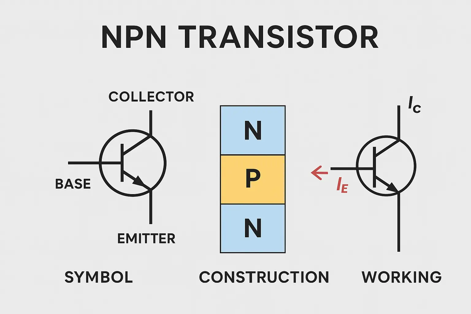
    An NPN transistor is a three-layer, three-terminal semiconductor device that consists of two n-type materials separated by a thin layer of p-type material. It is called “NPN” because of this specific arrangement of semiconductor layers — Negative-Positive-Negative.

    In this configuration, the emitter (E) and collector (C) are made of n-type semiconductor material, while the base (B) is a thin p-type region sandwiched between them. When properly biased, the NPN transistor allows electrons to flow easily from the emitter to the collector, enabling current amplification and switching functions.

    According to Morris Mano (Digital Design Expert), “The ability of a small input current to control a larger output current is what makes the transistor the heart of modern electronics.”

    Construction of NPN Transistor

    The construction of an NPN transistor involves three main regions, each performing a distinct role in the device’s operation:

    • Emitter (E): The emitter is heavily doped to inject a large number of free electrons into the base region.
    • Base (B): The base is very thin and lightly doped, allowing most electrons from the emitter to pass through to the collector.
    • Collector (C): The collector is moderately doped and larger in size to collect the electrons from the base region and dissipate heat effectively.

    The transistor is enclosed in a casing (metal or plastic) with three terminals corresponding to the emitter, base, and collector. The NPN transistor symbol features an arrow pointing outward on the emitter leg, representing the direction of conventional current flow (from base to emitter).

    NPN Transistor – symbol Working, Construction & Uses

    Working of NPN Transistor

    The working of an NPN transistor is based on charge carrier movement and junction biasing. It has two p-n junctions — the emitter-base junction (EBJ) and the collector-base junction (CBJ) — whose biasing determines transistor behavior.

    Active Mode Operation

    In the active region, the emitter-base junction is forward-biased, and the collector-base junction is reverse-biased. A small base current controls a much larger collector current, creating amplification.
    When a positive voltage is applied to the base relative to the emitter, electrons from the emitter move into the base region. Since the base is thin and lightly doped, most of these electrons cross into the collector region.

    This results in:

    • Base current (IB) – small control current
    • Collector current (IC) – large output current
    • Emitter current (IE) – total current (sum of IB and IC)

    Mathematically,
    IE = IB + IC
    and the current gain (β) is defined as:
    β = IC / IB

    Typical current gain values for NPN transistors range from 20 to 1000, depending on the transistor’s type and material.

    Cutoff and Saturation Regions

    In the cutoff region, both junctions are reverse-biased, and the transistor behaves like an open switch — no current flows through the device.
    In the saturation region, both junctions are forward-biased, allowing maximum current flow; the transistor behaves like a closed switch.

    This dual behavior enables NPN transistors to function as electronic switches in logic circuits, microcontrollers, and digital systems.

    Applications of NPN Transistor

    NPN transistors are among the most commonly used transistors in electronics because of their superior switching speed, high current gain, and ease of control. Some key applications include:

    Amplification

    NPN transistors are widely used as signal amplifiers in audio, radio, and communication devices. They can amplify small input voltages to much larger output voltages while maintaining signal integrity.

    Switching Circuits

    They act as solid-state switches in logic circuits, microcontrollers, and power regulators. When the base voltage is high, the transistor conducts (ON state), and when the base voltage is zero, it remains off (OFF state).

    Oscillators and Modulators

    Used in frequency generation and modulation circuits, NPN transistors help produce stable oscillations in radio transmitters and receivers.

    Current Control

    They regulate current flow in various devices, including sensors, relays, and automated control systems, by controlling a large load current through a small base current.

    Computers and Processors

    NPN transistors are fundamental elements in logic gates, amplifying circuits, and integrated circuits (ICs), forming the foundation of modern computing devices.

    Advantages of NPN Transistors

    NPN transistors are favored over PNP transistors in most designs because electrons, the majority carriers in NPNs, move faster than holes. This results in:

    • Higher efficiency and faster switching speeds
    • Better current handling capability
    • Simpler biasing with a positive voltage supply
    • Compatibility with TTL and CMOS logic families

    Conclusion

    The NPN transistor remains a cornerstone of modern electronics due to its versatility, speed, and efficiency. From acting as a reliable amplifier to serving as a high-speed digital switch, it plays a vital role in powering and controlling electronic systems. Understanding its construction, working, and applications not only provides a strong foundation for electrical engineering students but also enhances the design capability of professionals in electronics and automation fields.

    Most Popular NPN Transistors and Their Specifications

    Transistor Model Max Voltage (VCE) Max Current (IC) Power Dissipation (PD) Current Gain (hFE) Package Type Common Applications Special Features
    2N2222A 40V 800 mA 500 mW 75–30 TO-18 Signal amplification, RF circuits Fast switching, low noise
    BC547 45V 100 mA 500 mW 110–800 TO-92 Audio amplifiers, sensors Low leakage, stable operation
    2N3904 40V 200 mA 625 mW 100–300 TO-92 General-purpose switching High speed, low VCE(sat)
    BD139 80V 1.5 A 12.5 W 25–250 TO-126 Power amplifiers, drivers High current, medium power
    TIP31C 100V 3 A 40 W 10–50 TO-220 Power switching, audio amps High power, robust design
    2N3055 60V 15 A 115 W 20–70 TO-3 Regulators, inverters Excellent thermal stability
    BC337 45V 800 mA 625 mW 100–630 TO-92 LED drivers, control circuits High gain, reliable switching
    2N1711 50V 500 mA 800 mW 40–120 TO-39 RF and audio circuits High frequency response

    Frequently Asked Questions (FAQ)

    1. What is an NPN transistor used for?

    An NPN transistor is used for switching and amplification in electronic circuits. It controls large current flow through the collector using a small current at the base, making it essential in devices like amplifiers, logic circuits, and microcontrollers.

    2. How does an NPN transistor work?

    An NPN transistor works when a small base current allows a larger current to flow from the collector to the emitter. The emitter-base junction is forward-biased, and the collector-base junction is reverse-biased, enabling electron movement and current amplification.

    3. What is the symbol of an NPN transistor?

    The symbol of an NPN transistor has an arrow pointing outward on the emitter leg, indicating the direction of conventional current flow (from base to emitter). The three terminals are labeled as Emitter (E), Base (B), and Collector (C).

    4. What are the differences between NPN and PNP transistors?

    The NPN transistor uses electrons as majority carriers, while the PNP transistor uses holes. NPN transistors conduct when the base is positive relative to the emitter, whereas PNP transistors conduct when the base is negative relative to the emitter.

    5. Why is an NPN transistor preferred over a PNP transistor?

    NPN transistors are preferred because electrons move faster than holes, resulting in higher efficiency, faster switching speed, and simpler circuit design with a positive power supply. They are also more common in modern electronic applications.

    6. What is the current gain (β) in an NPN transistor?

    The current gain (β) is the ratio of the collector current (IC) to the base current (IB). It determines how effectively the transistor amplifies the current. Typical β values range from 20 to 1000, depending on the transistor type.

    7. Can an NPN transistor be used as a switch?

    Yes. In switching applications, when the base current is applied, the transistor goes into saturation mode (ON state), allowing full current through the collector. When no base current is applied, it enters cutoff mode (OFF state), stopping current flow.

    8. What materials are used to make NPN transistors?

    NPN transistors are made using silicon (Si) or gallium arsenide (GaAs) as semiconductor materials. Silicon-based transistors are more common because of their stability, cost-effectiveness, and thermal performance.

    Author’s comment

    So friends, I’m Pralay Bhunia, I hope I’ve been able to help you with this information about NPN Transistor (BJT). If you have any more questions or suggestions, please feel free to share them in the comments. Your support always inspires me to share more new information.

    External link

  • Bipolar Junction Transistor (BJT) – Working & Types

    Bipolar Junction Transistor (BJT) – Working & Types

    The Bipolar Junction Transistor, or BJT, is one of the most vital components in modern electronics. From amplifying signals in audio devices to switching operations in digital circuits, BJTs play a fundamental role in enabling the world of semiconductor technology. Developed in 1947 by John Bardeen, William Shockley, and Walter Brattain at Bell Labs, this invention transformed electronics and paved the way for the microelectronics revolution.

    What is a Bipolar Junction Transistor (BJT)?

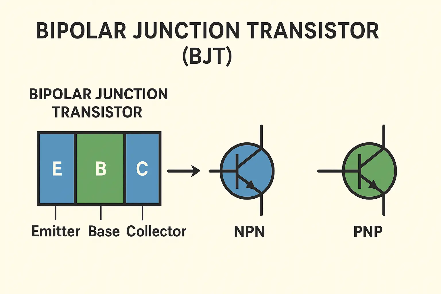
    A Bipolar Junction Transistor is a three-layer semiconductor device that uses both electrons and holes as charge carriers—hence the name bipolar. It consists of two p-n junctions connected back-to-back and can be of two types: NPN or PNP.
    BJTs are primarily used for signal amplification and electronic switching. Their ability to control large currents using small base signals makes them indispensable in analog and digital applications.

    Construction of Bipolar Junction Transistor

    A BJT has three regions and three terminals:

    • Emitter (E) – Heavily doped to inject charge carriers.
    • Base (B) – Very thin and lightly doped, allowing charge transfer.
    • Collector (C) – Moderately doped and larger in size to collect carriers.

    In an NPN transistor, two n-type materials sandwich a thin p-type base, while in a PNP transistor, two p-type materials surround an n-type base. The layers form two p-n junctions: the emitter-base junction and the collector-base junction.

    Operation of Bipolar Junction Transistor

    The working of a BJT depends on the biasing of its two junctions:

    • Emitter-Base Junction: Forward-biased to allow carrier injection.
    • Collector-Base Junction: Reverse-biased to enable carrier collection.

    When a small current flows through the base-emitter junction, it controls a much larger current between the collector and emitter. This property enables the transistor to act as an amplifier or a switch, depending on the configuration and input signal.

    Types of Bipolar Junction Transistor

    NPN Transistor

    In an NPN transistor, electrons are the majority charge carriers. When a positive voltage is applied to the base, it allows electrons to flow from emitter to collector, producing a controlled current flow. NPN types are commonly used due to higher electron mobility and efficiency.

    Read also:  NPN Transistor – Working, Construction & Uses

    PNP Transistor

    In a PNP transistor, holes serve as the majority charge carriers. Current flows from the emitter to the collector when the base is negatively biased relative to the emitter. PNP transistors are often used where negative polarity control is needed.

    Function of Bipolar Junction Transistor

    The BJT primarily functions as:

    • An Amplifier: It increases the amplitude of weak signals.
    • A Switch: It controls current flow in digital logic circuits and power control systems.
      Through precise base current control, a BJT can modulate or amplify signals with high accuracy.

    Voltage, Charge Control, and Current

    The BJT operates under the charge control principle, where the collector current is directly proportional to the charge injected into the base. The current gain (β) is defined as the ratio of collector current to base current (Ic/Ib).
    Typical β values range between 20 and 1000, depending on transistor design and application.

    Configuration of Bipolar Junction Transistors

    BJTs can be connected in three different configurations:

    • Common Base (CB) – Provides low input and high output impedance; used for high-frequency applications.
    • Common Emitter (CE) – Most widely used; provides voltage and current amplification.
    • Common Collector (CC) – Used for impedance matching; provides high input and low output impedance.

    Each configuration exhibits distinct input and output characteristics, determining its suitability for specific circuit functions.

    Characteristics of Transistor Configurations

    Configuration Input Impedance Output Impedance Current Gain Voltage Gain Application
    Common Base (CB) Low High < 1 High RF amplifiers
    Common Emitter (CE) Medium Medium High High Audio amplifiers, switches
    Common Collector (CC) High Low High < 1 Buffer circuits

    Applications of BJT

    Bipolar Junction Transistors are essential across various domains of electronics:

    • Signal Amplifiers: Used in radios, televisions, and audio systems.
    • Switching Circuits: Implemented in digital logic gates and control systems.
    • Voltage Regulation: Serve as control elements in regulators and power supplies.
    • Oscillators and Modulators: Used in waveform generation and communication circuits.
    • Microcontrollers and Processors: Form part of integrated circuits in computing devices.

    With the advancement of semiconductor materials and nanotechnology, BJTs continue to evolve for higher efficiency, smaller size, and greater frequency response.

    Conclusion

    The Bipolar Junction Transistor remains a cornerstone of modern electronics. Despite the rise of field-effect transistors (FETs), BJTs are still preferred in applications demanding high gain, precision, and linear amplification. Understanding their structure, operation, and characteristics provides a strong foundation for exploring advanced semiconductor technology.

    Frequently Asked Questions (FAQ)

    What is a Bipolar Junction Transistor (BJT) used for?

    A Bipolar Junction Transistor is used for amplifying weak electrical signals and switching electronic currents. BJTs are key components in audio amplifiers, oscillators, power regulators, and digital logic circuits.

    What are the two types of BJTs?

    There are two main types of Bipolar Junction TransistorsNPN and PNP.

    • In an NPN transistor, current flows from the collector to the emitter when a positive voltage is applied to the base.
    • In a PNP transistor, current flows from the emitter to the collector when the base is negatively biased.

    How does a BJT work?

    A BJT works by using a small base current to control a much larger current flowing between the collector and emitter. This property enables it to amplify signals or act as an electronic switch in various circuits.

    What are the three terminals of a BJT?

    The three terminals of a BJT are:

    • Emitter (E) – Injects charge carriers.
    • Base (B) – Controls the current flow.
    • Collector (C) – Collects the carriers and allows output current to flow.

    What is the difference between NPN and PNP transistors?

    The main difference lies in the direction of current flow and charge carriers:

    • NPN transistors use electrons as majority carriers and require a positive base voltage.
    • PNP transistors use holes as majority carriers and need a negative base voltage for operation.

    What are the main configurations of BJT?

    A BJT can be configured in three ways:

    • Common Base (CB) – High voltage gain, low current gain.
    • Common Emitter (CE) – Both voltage and current gain; most widely used.
    • Common Collector (CC) – Used as a buffer; provides current gain but no voltage gain.

    What are the applications of BJTs?

    BJTs are used in:

    • Amplifiers – Audio, RF, and instrumentation amplifiers.
    • Switching circuits – Digital logic and power control.
    • Voltage regulators – Stabilizing voltage in power supplies.
    • Oscillators and modulators – Generating and processing signals.

    What is the current gain (β) of a BJT?

    The current gain, represented by β (beta), is the ratio of collector current (Ic) to base current (Ib). It indicates how effectively the transistor amplifies current. Typical β values range from 20 to 1000 depending on transistor type and application.

    Author’s comment

    So friends, I’m Pralay Bhunia, I hope I’ve been able to help you with this information about Bipolar Junction Transistor (BJT). If you have any more questions or suggestions, please feel free to share them in the comments. Your support always inspires me to share more new information.

    External link

  • Inductors: Definition, Function, Types, and Working Explained

    Inductors: Definition, Function, Types, and Working Explained

    Inductors are among the most fundamental components in electrical and electronic systems. From simple circuits to advanced power electronics, inductors play a crucial role in controlling current, filtering signals, and storing magnetic energy. Understanding their construction, types, and behavior helps engineers design efficient and reliable electronic devices.

    What Is an Inductor?

    An inductor is a passive electrical component that stores energy in the form of a magnetic field when electric current passes through it. It resists sudden changes in current, making it essential for applications such as filtering, energy storage, and signal conditioning. The unit of inductance is the Henry (H), named after the American scientist Joseph Henry, who contributed to the discovery of electromagnetic induction alongside Michael Faraday.

    Construction of an Inductor

    An inductor typically consists of a coil of insulated wire wound around a core material. The core can be air, iron, or ferrite, depending on the desired magnetic properties. When current flows through the coil, a magnetic field forms around it. The number of turns in the coil and the core material determine the inductance value.
    The relationship between magnetic flux (Φ) and current (I) is expressed as L = Φ / I, where L is inductance. The higher the number of turns or the permeability of the core, the greater the inductance.

    Function of an Inductor

    The main function of an inductor is to oppose changes in current. It allows steady current flow but resists sudden fluctuations. When current increases, energy is stored in the magnetic field; when current decreases, the stored energy is released back into the circuit. This property makes inductors crucial in AC circuits, filters, power supplies, and transformers.

    inductor basic information ( definition, type of indicator, construction)

    Types of Inductors

    Iron Core Inductor

    The iron core inductor uses laminated or solid iron as the core material. Iron’s high magnetic permeability increases the magnetic field strength, providing high inductance. These inductors are used in transformers, power amplifiers, and energy conversion systems, where large inductance values are required.

    Air Core Inductor

    An air core inductor uses no magnetic material in the core—only air. Though it offers lower inductance, it eliminates core losses such as hysteresis and eddy currents. Air core inductors are ideal for high-frequency applications such as radio transmitters, RF circuits, and communication devices, where low distortion and high stability are essential.

    Iron Powder Inductor

    Iron powder inductors contain compressed iron particles mixed with a binder. They offer moderate inductance with reduced core losses compared to solid iron cores. They are widely used in switching power supplies, DC-DC converters, and filter circuits due to their efficiency and compact design.

    Ferrite Core Inductor

    Ferrite core inductors are among the most common types in modern electronics. They use a ferrite material—a ceramic-like compound made from iron oxide and other metals—to enhance magnetic performance and reduce losses. Ferrite inductors are divided into two main categories:

    Soft Ferrite Inductor

    Soft ferrites have low coercivity, meaning they can easily magnetize and demagnetize. They are used in transformers, chokes, and filter circuits, particularly in high-frequency switching systems.

    Hard Ferrite Inductor

    Hard ferrites, also called permanent ferrites, have high coercivity and retain their magnetization. These are used in permanent magnets, magnetic sensors, and inductive components requiring stable magnetic properties.

    Working Principle of an Inductor

    The working of an inductor is based on Faraday’s Law of Electromagnetic Induction, which states that a changing magnetic field induces an electromotive force (EMF) in the conductor. When current flows through the coil, a magnetic field builds up around it. If the current changes, the inductor generates an induced voltage that opposes the change in current—this phenomenon is known as self-induction.

    Mathematically, the induced voltage (V) is expressed as:
    V = -L (dI/dt)
    where L is inductance, dI/dt is the rate of change of current, and the negative sign indicates opposition to current change.

    Controlling Signals with Inductors

    In electronic circuits, inductors act as low-pass filters, allowing low-frequency signals to pass while blocking high-frequency noise. This makes them valuable in audio systems, communication networks, and power supplies, where signal stability is essential. In combination with capacitors, inductors form LC circuits, which are used in tuning and resonance applications, such as radio receivers and oscillators.

    Storing Energy in an Inductor

    When an electric current flows through an inductor, it stores energy in the magnetic field surrounding the coil. The stored energy (E) is calculated using the formula:
    E = (1/2) L I²
    This energy is released back to the circuit when the current decreases, allowing inductors to act as temporary energy reservoirs. This feature is crucial in switch-mode power supplies, pulse circuits, and energy recovery systems.

    Applications of Inductors

    Inductors are used in a wide range of applications, including power electronics, radio frequency circuits, transformers, electric vehicles, and renewable energy systems. They play a vital role in reducing electrical noise, stabilizing voltage, and ensuring smooth current flow in both AC and DC circuits.

    Conclusion

    Inductors represent the perfect blend of simplicity and functionality in modern electronics. Their ability to control, store, and manage electrical energy makes them essential in both small-scale circuits and large industrial systems. As technology advances, inductor design continues to evolve, with materials and shapes optimized for higher efficiency and smaller form factors—supporting the next generation of smart, energy-efficient devices.

    Frequently Asked Questions (FAQ)

    What is an inductor used for?

    An inductor stores energy in its magnetic field when current flows through it and then releases that energy when the current changes. It is employed in circuits to filter noise, smooth power supply ripple, block high-frequency signals while passing low-frequency ones, and aid in resonance and impedance matching.

    How does an inductor (coil) function in a circuit?

    When current in a coil changes, a voltage (emf) is induced that opposes the change in current (Lenz’s law). This self-induction behavior causes the inductor to resist sudden current fluctuations while allowing steady currents to flow more easily.

    Can inductors block current or limit current?

    While inductors do not act like resistors, they resist changes in current. In AC circuits, inductors offer higher impedance at higher frequencies, effectively “blocking” or attenuating rapid current changes or high-frequency components. They are often used as “chokes” to isolate unwanted signals.

    What is a choke in electronics?

    A choke is a specialized inductor used to block or “choke” high-frequency AC while allowing DC or low-frequency current to pass. It’s designed with characteristics optimized for filtering rather than tuning or resonance.

    What is the self-resonant frequency of an inductor?

    An inductor has parasitic capacitances between its turns. At a certain frequency, its inductive reactance equals the capacitive reactance, and the component resonates. That frequency is known as the self-resonant frequency (SRF). Above SRF, its behavior changes and it ceases to act purely inductively.

    When do inductors store energy vs release energy?

    Inductors store energy when current through them increases; that energy is held in the magnetic field. When current decreases, the magnetic field collapses and the stored energy is released back into the circuit. In AC circuits, this storing and releasing happens continuously every cycle.

    How do inductors help in tuned circuits?

    Inductors combined with capacitors form LC circuits (resonant or tuned circuits). At a resonant frequency, inductive and capacitive reactances cancel, allowing selective frequencies to pass or oscillate. Such circuits are critical in radio, TV, and communication systems for frequency selection.

    Author’s comment

    So friends, I’m Pralay Bhunia, I hope I’ve been able to help you with this information about Indicator. If you have any more questions or suggestions, please feel free to share them in the comments. Your support always inspires me to share more new information.

    External link

  • Air Compressor: Types, Function, and Working Explained

    Air Compressor: Types, Function, and Working Explained

    An air compressor is one of the most versatile and essential machines in both industrial and domestic applications. It transforms mechanical power into potential energy stored in pressurized air, which can then be used for countless purposes—from powering pneumatic tools to manufacturing, painting, and construction. Its efficiency, reliability, and adaptability make it an indispensable component across modern industries.

    What is an Air Compressor

    An air compressor is a mechanical device that increases the pressure of air by reducing its volume. It converts electrical or mechanical energy into compressed air, which stores potential energy that can be released to perform various tasks. According to thermodynamic principles, compression raises both the pressure and temperature of air, making it a controlled source of power.

    Function of an Air Compressor

    The main function of an air compressor is to supply compressed air for operating pneumatic equipment and tools. When air is compressed, it becomes dense and stores energy. Upon release, this air can be used to drive mechanical systems, clean surfaces, spray paint, inflate tires, or operate industrial machines. Compressed air is often referred to as the “fourth utility” after electricity, gas, and water, due to its widespread use in modern facilities.

    Types of Air Compressors and Their Working

    Reciprocating (Piston) Air Compressors

    These compressors use a piston driven by a crankshaft to compress air within a cylinder. As the piston moves down, it draws air into the chamber; when it moves up, the air is compressed and forced into a storage tank. Reciprocating compressors are ideal for intermittent use and are commonly found in workshops and automotive garages.

    Rotary Screw Air Compressors

    Rotary screw compressors use two interlocking helical rotors to compress air continuously. They are designed for constant operation, offering smooth, quiet, and energy-efficient performance. These compressors are widely used in industrial production lines and large-scale pneumatic systems.

    Centrifugal Air Compressors

    Centrifugal compressors use high-speed impellers to accelerate air outward and convert velocity into pressure energy. They are suited for large-scale, continuous-duty applications such as in power plants, refineries, and chemical industries.

    Scroll Air Compressors

    Scroll compressors use two spiral-shaped elements—one fixed and one moving—to compress air. They operate quietly and are highly efficient, making them suitable for medical, laboratory, and precision manufacturing environments.

    Working Principle

    The working principle of an air compressor is based on Boyle’s Law, which states that the pressure of a gas increases as its volume decreases, provided temperature remains constant. The compressor draws in atmospheric air, traps it in a confined space, and reduces the volume to increase pressure. This pressurized air is then cooled, filtered, and stored in a tank for use. Depending on design, compressors can operate in single-stage or multi-stage modes to achieve desired pressure levels.

    Power Supply and Energy Source

    Air compressors are powered by various energy sources depending on their design and application. The most common are electric motors, used for stationary and indoor setups, and diesel or gasoline engines, preferred for portable and outdoor operations. Modern industrial compressors may also use turbine drives for large-scale energy production. Energy efficiency plays a crucial role in compressor operation, as compressed air systems account for nearly 10% of total industrial energy consumption worldwide, according to the U.S. Department of Energy.

    Applications and Importance

    Air compressors are vital across numerous sectors—manufacturing, automotive, healthcare, construction, and agriculture. They power tools, automate production lines, support HVAC systems, and provide energy for pneumatic control in aircraft and submarines. The reliability of compressed air ensures operational continuity where precision and consistency are essential.

    Conclusion

    The air compressor is a symbol of mechanical ingenuity—simple in concept yet critical in execution. From powering industrial machinery to supporting home workshops, it stands as a silent force behind modern productivity. As industries shift toward energy efficiency and automation, innovations in compressor design will continue to enhance performance, sustainability, and reliability.

    Frequently Asked Questions (FAQ)

    What does an air compressor do?

    An air compressor converts power—often from an electric motor or internal combustion engine—into compressed air by reducing its volume. The stored pressurized air can then be released to perform work, such as powering pneumatic tools or inflating tires.

    What are the different types of air compressors?

    Air compressors come in several types, each suited to different tasks. Major categories include reciprocating (piston) compressors, rotary screw compressors, and centrifugal compressors. Some compressors also employ variable-speed drive (VSD) control to enhance energy efficiency.

    Which air compressor type is best for my needs?

    The best air compressor depends on how you plan to use it. For intermittent household or workshop tasks, a reciprocating compressor may suffice. For continuous, high-demand operations, a rotary screw or centrifugal compressor is more appropriate. You should also consider factors such as required pressure (PSI), airflow (CFM), tank size, noise levels, and whether you need oil-free or lubricated operation.

    What is CFM and PSI, and why are they important in compressors?

    CFM (Cubic Feet per Minute) measures the volumetric airflow a compressor delivers, while PSI (Pounds per Square Inch) indicates air pressure. Both metrics matter because tools and applications require specific combinations of airflow and pressure. A compressor must meet or exceed the CFM and PSI demands of tools it will supply.

    What are the advantages of using compressed air versus electric or hydraulic power?

    Compressed air offers safety advantages (no electrical shock risk), flexibility in routing power through pipes, and the ability to regulate pressure for different tasks. Pneumatic tools tend to be lighter and more durable than electric motors. Compressed air systems can also be extended or modified more easily than wiring or hydraulic lines.

    What power sources are used for air compressors?

    Air compressors can be driven by electric motors, diesel engines, gasoline engines, or even turbine drives, depending on application and location. Portable compressors, especially for construction or remote work, often use diesel or gasoline.

    How do I size a compressor for my project?

    Sizing involves determining the required airflow (CFM) and pressure (PSI) for your tools or systems. Add up the peak demands of all tools you may run simultaneously, then add a safety margin. Also consider duty cycles (how often the compressor runs) and storage tank capacity.

    What are the maintenance requirements for air compressors?

    Key maintenance tasks include checking and changing oil (in lubricated models), draining condensation from tanks, cleaning or replacing air filters, inspecting hoses and connections, and monitoring for leaks. These steps help maintain efficiency and longevity.

    What is a variable-speed drive (VSD) compressor and why use it?

    A VSD compressor adjusts motor speed in response to demand, rather than operating at full speed constantly. This results in energy savings—especially in systems with variable load—since the compressor only works as hard as needed.

    Are there special compressor types for clean air applications (food, medical)?

    Yes. Oil-free compressors or specially filtered systems are used in applications requiring ultra-clean air, such as medical, pharmaceutical, and food processing industries, to avoid contamination from oil or particulates.

    Author’s comment

    So friends, I’m Pralay Bhunia, I hope I’ve been able to help you with this information about Air Compressor. If you have any more questions or suggestions, please feel free to share them in the comments. Your support always inspires me to share more new information.

    External link

  • Electricity: Definition, History, Production, and Uses Explained

    Electricity: Definition, History, Production, and Uses Explained

    Electricity is one of the most fundamental forces shaping the modern world. It powers our homes, industries, and digital technologies, forming the backbone of contemporary civilization. From a flick of a switch to the operation of satellites, electricity represents both a basic physical phenomenon and an essential utility for progress. Its invisible power connects humanity to innovation, communication, and comfort, making it one of the most transformative discoveries in human history.

    What is electricity (only definition)

    Electricity is a form of energy resulting from the movement or accumulation of charged particles, such as electrons or ions, within a conductor or field.

    History of Electricity

    The story of electricity is a journey from curiosity to control. Ancient civilizations, including the Greeks, observed static electricity by rubbing amber with fur, giving rise to the term “electron,” derived from the Greek word for amber. In the 17th and 18th centuries, scientists like William Gilbert, Benjamin Franklin, and Alessandro Volta deepened humanity’s understanding of electric forces. Franklin’s kite experiment demonstrated that lightning was a form of electricity, while Volta’s invention of the Voltaic pile in 1800 marked the creation of the first chemical battery.
    The 19th century saw rapid progress, with pioneers like Michael Faraday and James Clerk Maxwell uncovering the relationship between electricity and magnetism, leading to the invention of electric generators. Later, Thomas Edison and Nikola Tesla revolutionized electric power distribution—Edison championing direct current (DC) and Tesla introducing alternating current (AC), which became the foundation of modern electrical systems.

    Concepts and Nature of Electricity

    Electricity arises from the movement of electrons through a conductor. It is a form of energy resulting from charged particles, either stationary (static electricity) or in motion (current electricity). The two main types of current are direct current (DC), which flows steadily in one direction, and alternating current (AC), which changes direction periodically. The flow of electrons generates voltage, current, and resistance—key principles that define electrical behavior according to Ohm’s Law (V = IR).

    Production of Electricity

    Electricity production relies on converting mechanical, chemical, or thermal energy into electrical energy. The most common method is through electromagnetic induction, discovered by Faraday, where rotating turbines generate electricity using magnets and coils.
    Power plants use various energy sources:

    • Fossil fuels (coal, oil, natural gas) produce steam to drive turbines.
    • Renewable sources, such as wind, solar, and hydropower, harness natural forces to create clean electricity.
    • Nuclear power relies on controlled fission reactions to generate immense energy with minimal carbon emissions.
      As of recent decades, the world has increasingly shifted toward renewable energy, with over 30% of global electricity generation now coming from sustainable sources, according to the International Energy Agency (IEA).

    Storage of Electricity

    Electricity cannot be stored directly; instead, it is converted into other energy forms for storage. Batteries store electrical energy chemically, while capacitors store it electrostatically. Large-scale solutions like pumped hydroelectric storage, compressed air systems, and lithium-ion battery grids are essential for balancing supply and demand in modern power networks. The future of energy stability lies in advancing battery technologies for renewable integration and electric vehicles.

    Uses of Electricity

    Electricity powers nearly every aspect of modern life. It fuels industries, lights cities, drives communication networks, and supports healthcare, education, and entertainment. It also enables technologies like computers, smartphones, and the Internet of Things (IoT). In agriculture, electricity powers irrigation and storage; in transportation, it drives the shift toward electric vehicles (EVs) for cleaner mobility. The World Bank estimates that over 90% of the global population now has access to electricity, highlighting its essential role in human development.

    Electricity and the Natural World

    Electricity is not just a human invention; it is a natural phenomenon. Lightning is a spectacular example of nature’s electric power, discharging millions of volts in a fraction of a second. Many animals, such as electric eels and rays, generate and use electricity for hunting or defense—a process known as bioelectrogenesis. Even the human body relies on tiny electric impulses transmitted by neurons to control movement and thought.

    Cultural Perception of Electricity

    Throughout history, electricity has symbolized enlightenment, progress, and innovation. In the 19th century, the glow of electric light became a metaphor for knowledge and modernity. Today, electricity is seen as a universal right and a measure of societal advancement. Yet, it also carries responsibility—our dependence on electrical energy demands sustainable production and mindful consumption. As Nikola Tesla once said, “If you want to find the secrets of the universe, think in terms of energy, frequency, and vibration.”

    Conclusion

    Electricity is more than a scientific discovery; it is a cornerstone of modern civilization and a force of nature that defines human progress. From its natural origins to its industrial and digital applications, electricity connects humanity to innovation, comfort, and the future. As global societies strive toward sustainability, the challenge remains to harness this invisible power responsibly—ensuring that the light of progress continues to shine for generations to come.

    Frequently Asked Questions (FAQ)

    What is electricity in simple words?

    Electricity is a form of energy created by the movement of charged particles, such as electrons. It powers lights, machines, and almost everything we use daily.

    Who discovered electricity?

    Electricity was not discovered by a single person but understood through the contributions of many scientists. Ancient Greeks observed static electricity, while Benjamin Franklin demonstrated its lightning connection. Later, Alessandro Volta, Michael Faraday, and James Clerk Maxwell laid the foundation for modern electrical science.

    How is electricity produced?

    Electricity is produced by converting other forms of energy—mechanical, chemical, or thermal—into electrical energy. This is mainly done through electromagnetic induction, where turbines spin inside generators powered by steam, water, wind, or nuclear reactions.

    What are the main sources of electricity?

    The main sources of electricity include fossil fuels (coal, oil, natural gas), renewable energy (solar, wind, hydro, geothermal), and nuclear power. The world is increasingly moving toward renewable and clean energy sources to reduce pollution.

    How is electricity stored?

    Electricity is stored using devices that convert it into another form of energy. Batteries store electrical energy chemically, capacitors store it electrostatically, and pumped hydro systems store it as gravitational potential energy.

    Why is electricity important?

    Electricity is essential because it powers industries, homes, communication systems, and healthcare technologies. It supports economic growth and improves quality of life across all aspects of modern society.

    What is the difference between current and voltage?

    Current is the flow of electric charge, while voltage is the potential difference that drives that flow. Voltage can be thought of as the “push,” and current as the “movement” of electrons.

    What are the types of electricity?

    There are two main types: Static electricity, which stays in one place, and Current electricity, which flows through conductors. Current electricity can further be divided into Direct Current (DC) and Alternating Current (AC).

    Can electricity be found in nature?

    Yes, electricity occurs naturally. Lightning is a powerful form of natural electricity, and certain animals, such as electric eels, rays, and even our own nervous system, use electrical signals for survival and communication.

    What is the future of electricity?

    The future of electricity is centered around renewable energy, smart grids, and energy storage technologies. As countries aim for carbon neutrality, electricity will become cleaner, more efficient, and more digitally managed through AI and IoT innovations.

    Author’s comment

    So friends, I’m Pralay Bhunia, I hope I’ve been able to help you with this information about What is Electricity. If you have any more questions or suggestions, please feel free to share them in the comments. Your support always inspires me to share more new information.

    External link

  • Springs: Definition, Types, Materials, and Applications

    Springs: Definition, Types, Materials, and Applications

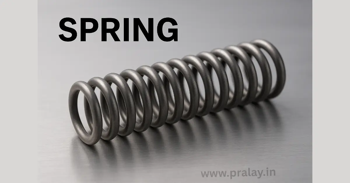
    Springs are among the simplest yet most essential mechanical devices used in engineering and daily life. From suspension systems in vehicles to the click of a ballpoint pen, springs play a critical role in storing and releasing energy, absorbing shock, and maintaining force. Despite their simplicity, they have enabled countless innovations in mechanics, physics, and technology.

    Definition of a Spring

    What is a spring? A spring is a flexible, elastic device made of resilient material that stores mechanical energy when deformed and releases it when returning to its original shape. The principle of a spring is based on Hooke’s Law, which states that the force exerted by a spring is directly proportional to its extension or compression, provided the elastic limit is not exceeded.

    Examples of Springs in Daily Life

    Springs are used everywhere: in watches, mattresses, vehicle suspensions, machinery, toys, medical devices, and industrial systems. Each example demonstrates how springs provide controlled motion, absorb impact, or maintain tension.

    Types of Springs

    Compression Springs

    Compression springs are designed to resist compressive forces. Found in mattresses, automotive suspensions, and shock absorbers, they store energy when compressed and release it upon expansion.

    Extension Springs

    Extension springs absorb and store energy when pulled apart. They are commonly used in trampolines, screen doors, and weighing scales.

    Torsion Springs

    These springs operate by twisting around their axis. They are widely used in clothespins, mousetraps, and mechanical hinges.

    Constant-Force Springs

    Made from a tightly wound strip of metal, these springs provide a constant force regardless of extension. They are used in cable retractors and tape measures.

    Leaf Springs

    Flat and curved, leaf springs are primarily used in vehicle suspension systems to support heavy loads and absorb shocks.

    Materials Used for Springs

    Springs are typically made from materials that exhibit elasticity, durability, and fatigue resistance. The most common materials include:

    • High-carbon steel (such as music wire and oil-tempered steel) for high strength.
    • Stainless steel for corrosion resistance.
    • Phosphor bronze and beryllium copper for electrical conductivity and resistance to wear.
    • Nickel-based alloys for high-temperature applications.

    Material selection depends on the working environment, load conditions, and required durability.

    Properties of Springs

    Springs are characterized by elasticity, stiffness (spring constant), fatigue life, and resistance to environmental stress. Their design must balance flexibility with strength to ensure safe and efficient performance.

    Uses of Springs in Engineering and Daily Life

    Springs are crucial in mechanical engineering, electronics, and household products. They absorb shocks in vehicles, regulate motion in machinery, ensure contact in electrical devices, and provide comfort in bedding and seating. In modern technology, micro-springs are also integrated into MEMS (Microelectromechanical Systems) used in sensors and actuators.

    Conclusion

    Springs may appear simple, but they are indispensable in countless fields. By storing and releasing energy, they ensure safety, efficiency, and reliability across industries. Whether in a wristwatch or an aircraft, springs prove that even the smallest components can have the greatest impact.

    Frequently Asked Questions (FAQ)

    What is a spring device used for?

    A spring device is used to store and release mechanical energy, absorb shock, apply force, or maintain tension. Springs are commonly found in vehicles, machinery, electronics, and household items.

    What are the most common types of springs?

    The most common types of springs are compression springs, extension springs, torsion springs, constant-force springs, and leaf springs. Each type serves different mechanical functions depending on the load and application.

    What is the best material for making springs?

    The best material for springs depends on their use. High-carbon steel (like music wire) is widely used for strength, stainless steel is preferred for corrosion resistance, and phosphor bronze is used for electrical conductivity.

    Which type of spring is used in vehicles?

    Vehicles mainly use coil springs, leaf springs, and torsion bars in suspension systems. These springs absorb shocks, improve ride comfort, and provide stability during driving.

    What is the strongest type of spring?

    The strength of a spring depends on its material, design, and application. Heavy-duty compression springs made of high-carbon or alloy steel are considered the strongest and are used in industrial machinery and heavy vehicles.

    What are some examples of springs in daily life?

    Examples include pens, mattresses, trampolines, clothespins, watches, weighing machines, and door locks. These show how springs are essential in both simple and complex devices.

    How does a spring work?

    A spring works on the principle of Hooke’s Law, which states that the force exerted by the spring is proportional to its displacement. When compressed, stretched, or twisted, the spring stores energy and releases it when returning to its original shape.

    What is the lifespan of a spring?

    The lifespan of a spring depends on its material, design, and working conditions. High-quality springs can last millions of cycles if used within their elastic limit, while poor-quality or overstressed springs may fail quickly.

    Author’s comment

    So friends, I’m Pralay Bhunia, I hope I’ve been able to help you with this information about Springs. If you have any more questions or suggestions, please feel free to share them in the comments. Your support always inspires me to share more new information.

    External link

  • Insulators: Definition, Types, Properties, and Applications

    Insulators: Definition, Types, Properties, and Applications

    Electricity powers our modern lives, but not all materials conduct it. While conductors and semiconductors allow the flow of current, insulators are materials that resist it. Their unique role is to protect, separate, and prevent unintended current flow, ensuring both safety and efficiency. From the rubber covering electrical wires to the ceramic discs on high-voltage transmission lines, insulators are everywhere in daily life.

    What is an Insulator?

    An insulator is a material that resists the flow of electric current because its electrons are tightly bound to atoms and cannot move freely. Unlike conductors, which have free electrons, insulators provide resistance and act as barriers against the flow of electricity.

    See also: Semiconductor

    Examples of Insulators

    Common insulators include:

    • Non-metals such as rubber, plastic, glass, and wood.
    • Ceramics like porcelain, widely used in power systems.
    • Mica and paper, used in capacitors and insulation layers.
    • Air, which acts as a natural insulator under normal conditions.

    Atomic Structure and Band Theory of Insulators

    In an insulator, electrons in the valence band are tightly bound to their atoms, and the band gap separating the valence band from the conduction band is very large (greater than 4 eV). This wide band gap makes it nearly impossible for electrons to gain enough energy to move into the conduction band, resulting in poor electrical conductivity.

    Properties of Insulators

    • High electrical resistance prevents the flow of current.
    • High dielectric strength allows them to withstand large voltages without breaking down.
    • Low thermal conductivity in many cases, offering both electrical and heat insulation.
    • Durability and strength make them suitable for long-term use in harsh conditions.

    Types of Insulators

    Solid Insulators

    Examples include rubber, glass, plastic, porcelain, and mica. These are widely used in cables, switches, and circuit boards.

    Liquid Insulators

    Mineral oils and transformer oils are used to insulate and cool electrical equipment.

    Gaseous Insulators

    Air, nitrogen, and sulfur hexafluoride (SF₆) serve as insulating gases in high-voltage systems.

    Applications of Insulators

    A Electric insulators images
    A Electric insulators images

    Electrical Wiring and Cables

    Rubber and plastic coatings insulate copper or aluminum wires, preventing current leakage and ensuring safety.

    Power Transmission

    Porcelain and glass insulators are mounted on transmission towers to prevent current leakage and mechanical failure of high-voltage lines.

    Household Appliances

    Everyday devices such as chargers, refrigerators, and toasters use insulating materials to protect users from electric shocks.

    Electronics and Capacitors

    Mica and ceramic materials are used in capacitors to store charge without allowing current leakage.

    Industrial and Safety Equipment

    High-voltage gloves, insulating mats, and protective coatings use insulating materials to ensure worker safety.

    Insulators are just as vital as conductors and semiconductors in the electrical world. While conductors enable the flow of current and semiconductors control it, insulators protect against unwanted current flow. By ensuring safety, efficiency, and reliability, insulators form the protective shield of modern technology. From power grids to household wiring, they are indispensable in making electricity safe and useful.

    See also: Conductor

    Frequently Asked Questions (FAQ)

    What is an insulator in simple words?

    An insulator is a material that does not allow electricity to flow through it easily. Examples include rubber, glass, wood, and plastic.

    What are the main uses of insulators?

    Insulators are used to cover electrical wires, prevent electric shocks, support transmission lines, and ensure the safe operation of electrical and electronic devices.

    What is the difference between a conductor and an insulator?

    A conductor allows the flow of electricity because it has free electrons, while an insulator resists current flow because its electrons are tightly bound to atoms.

    Which materials are the best electrical insulators?

    Rubber, glass, plastic, porcelain, mica, and dry wood are considered excellent insulators due to their high resistance and durability.

    What is the role of insulators in power transmission lines?

    Insulators made of porcelain or glass support high-voltage power lines, preventing electricity from leaking into the towers or the ground.

    Do insulators have a band gap?

    Yes, insulators have a very wide band gap, usually greater than 4 electron volts (eV), which prevents electrons from moving into the conduction band.

    Can air act as an insulator?

    Yes, under normal conditions, air is a good insulator. However, when the voltage becomes very high, air can break down and allow current to pass through, leading to sparks or lightning.

    Are all non-metals insulators?

    Not all non-metals are perfect insulators, but many (like rubber, glass, and plastics) are widely used because they resist the flow of electricity.

    Author’s comment

    So friends, I’m Pralay Bhunia, I hope I’ve been able to help you with this information about Insulators. If you have any more questions or suggestions, please feel free to share them in the comments. Your support always inspires me to share more new information.

    External link

    Physics Electrical InsulatorsSATHEE – IIT Kanpur

  • What are Electrical Conductors? Types, Properties, Examples & Uses

    What are Electrical Conductors? Types, Properties, Examples & Uses

    Learn what electrical conductors are, their types, properties, examples, and real-life uses. Beginner-friendly guide with comparison and FAQs.

    What are Electrical Conductors?

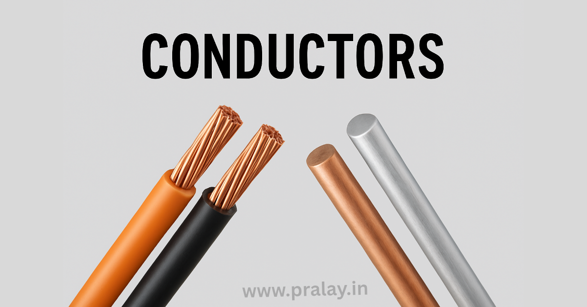
    Electrical conductors are materials that allow electric current to flow through them easily. This happens because conductors contain a large number of free electrons that can move freely within the material. When a voltage is applied, these electrons start moving and create an electric current.

    In simple terms, a conductor is a material that offers very little resistance to the flow of electricity. This is why conductors are widely used in electrical wiring, circuits, and almost every electronic device we use in daily life.

    How Do Conductors Work?

    The working of electrical conductors is based on the movement of electrons. In conductive materials, electrons are loosely bound to atoms, which allows them to move freely when an electric field is applied.

    For example, when a copper wire is connected to a battery, the electric field pushes electrons through the wire. This continuous movement of electrons forms an electric current, which powers devices like bulbs, fans, and chargers.

     Types of Electrical Conductor

    Electrical conductors can be classified into different types based on how they conduct electricity. Metallic conductors, such as copper and aluminum, are the most commonly used because they have a high number of free electrons. These materials are widely used in electrical wiring and circuits.

    Electrolytic conductors, on the other hand, conduct electricity through ions rather than electrons. A common example is saltwater, where charged particles carry the current. There are also superconductors, which are special materials that can conduct electricity with zero resistance under specific conditions. These are used in advanced technologies like MRI machines and research applications.

    There are different types of conductors:

    1. Metallic Conductors

    • Examples: Copper, Aluminum, Silver
    • Used in wiring and circuits

    2. Electrolytic Conductors

    • Conduct electricity through ions
    • Example: Saltwater

    3. Superconductors

    • Offer zero resistance
    • Used in advanced technologies

    Properties of Electrical Conductors

    Conductors have several important properties that make them suitable for electrical applications. They have high electrical conductivity, which means they allow current to pass easily. At the same time, they have low resistance, so very little energy is lost during the flow of electricity.

    Another key property is the presence of free electrons, which are responsible for carrying electric charge. Many conductors also have good thermal conductivity, allowing them to transfer heat efficiently along with electricity.

    Examples of Conductors

    Material Conductivity
    Silver Highest
    Copper Very high
    Aluminum Good
    Gold Moderate

    Conductors vs Insulators

    Conductors and insulators are opposite in nature. While conductors allow electric current to flow easily, insulators resist the flow of electricity. Materials like copper and silver are good conductors, whereas rubber and plastic are commonly used as insulators.

    This difference is very important in electrical systems. Conductors are used to carry current, while insulators are used to protect and prevent unwanted flow of electricity.

    Feature Conductors Insulators
    Current Flow Easy Difficult
    Resistance Low High
    Examples Copper, Silver Rubber, Plastic

    Applications of Conductors

    Electrical conductors play a crucial role in everyday life. They are used in house wiring to deliver electricity to different appliances. Power transmission lines use conductors to carry electricity over long distances. Inside electronic devices, conductors connect different components and ensure proper functioning.

    Without conductors, it would not be possible to use electricity safely and efficiently in homes, industries, or technology.

    Conclusion

    Electrical conductors are essential materials that make the flow of electricity possible. Their ability to allow free movement of electrons makes them a key component in all electrical and electronic systems. From simple household wiring to complex industrial machines, conductors are everywhere.

    Understanding how conductors work, their types, and their properties is important for building a strong foundation in electrical and electronic engineering.

    Read also:

    FAQ

    Q1: What is an electrical conductor?

    A conductor is a material that allows electricity to flow easily.

    Q2: What are examples of conductors?

    Copper, aluminum, silver, and gold.

    Q3: Why are metals good conductors?

    Because they have free electrons that move easily.

    Q4: What is the difference between conductor and insulator?

    Conductors allow current, while insulators block it.

    Reference: Electrical Conductors – IIT Kanpur

  • Semiconductor: Types, Properties, and Applications

    Semiconductor: Types, Properties, and Applications

    The semiconductor is one of the most influential materials in the modern world, powering everything from smartphones and computers to medical devices and satellites. Without semiconductors, the digital revolution would not have been possible. According to the Semiconductor Industry Association, global semiconductor sales surpassed $580 billion in 2022, reflecting their vital role in technology and economic growth. To understand why semiconductors are so important, it is essential to explore their definition, properties, and diverse applications.

    What is a Semiconductor?

    A semiconductor is a material whose electrical conductivity lies between that of a conductor, like copper, and an insulator, like glass. Its unique property is that conductivity can be controlled by temperature, light, and impurity addition, making it the backbone of electronic devices. Common semiconductor materials include silicon, germanium, and gallium arsenide.

    Examples of Semiconductors

    The most widely used semiconductor is silicon, due to its abundance and cost-effectiveness. Germanium and gallium arsenide are also used in specialized applications such as high-speed devices and optoelectronics.

    Materials Used in Semiconductors

    Silicon dominates the semiconductor industry because of its stability and oxide-forming ability, which is crucial in integrated circuits. Gallium arsenide is preferred for devices requiring faster operation and higher efficiency, such as in satellites and radar systems.

    Holes and Electrons in Semiconductors

    In semiconductors, the flow of electricity is controlled by two charge carriers: electrons and holes. An electron is a negatively charged particle, while a hole is the absence of an electron that behaves as a positive charge carrier. Together, these carriers determine the current conduction.

    Band Theory of Semiconductors

    Band theory explains how electrons occupy different energy levels. In semiconductors, the valence band is filled with electrons, while the conduction band is where free electrons can move. The gap between them, called the band gap, is small enough for electrons to jump across when energy is applied, allowing conduction.

    Properties of Semiconductors

    Semiconductors exhibit distinct properties, such as variable conductivity, sensitivity to temperature, and the ability to respond to light and magnetic fields. These properties make them ideal for designing transistors, diodes, and solar cells.

    Semiconductor Chemistry Fundamentals

    The study of semiconductors is deeply rooted in chemistry and solid-state physics. To understand how semiconductors function in modern electronics, it is essential to explore their chemical structure, bonding, and the role of electrons and holes. Semiconductor chemistry provides the foundation for innovations such as transistors, diodes, solar cells, and microprocessors.

    Atomic Structure and Bonding in Semiconductors

    the atomic structure of silicon showing Covalent bonds in a crystal lattice
    the atomic structure of silicon showing Covalent bonds in a crystal lattice

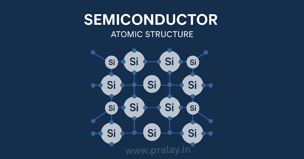
    Semiconductors like silicon (Si) and germanium (Ge) belong to Group 14 of the periodic table. Each atom has four valence electrons, allowing them to form covalent bonds with neighboring atoms in a crystal lattice. This stable arrangement creates a crystalline solid with unique electrical properties.

    When the temperature rises, some of these covalent bonds break, freeing electrons and creating holes. This dynamic between bound and free electrons is the key to semiconductor conductivity.

    Band Gap in Semiconductor Chemistry

    A fundamental concept is the band gap (Eg), which is the energy difference between the valence band (where electrons are bound) and the conduction band (where electrons move freely).

    • Conductors have overlapping bands (no gap).
    • Insulators have a wide band gap (>4 eV).
    • Semiconductors have a moderate band gap (usually between 0.5 eV and 3 eV).

    For example:

    • Silicon has a band gap of 1.1 eV.
    • Germanium has a band gap of 0.7 eV.
    • Gallium arsenide (GaAs) has a band gap of 1.4 eV.

    This moderate band gap allows semiconductors to conduct electricity under specific conditions, making them ideal for controlled electronic devices.

    Role of Doping in Semiconductor Chemistry

    Doping is a chemical process where small amounts of impurities are introduced into a pure semiconductor (intrinsic). This creates extrinsic semiconductors with enhanced conductivity.

    N-type doping: Adding Group 15 elements like phosphorus or arsenic introduces extra electrons.

    P-type doping: Adding Group 13 elements like boron or aluminum creates more holes.

    Types of Semiconductors

    Semiconductors can be classified into two major categories: intrinsic and extrinsic.

    Intrinsic Semiconductor

    An intrinsic semiconductor is a pure form of material without impurities. Its conductivity depends entirely on temperature and light. Silicon and germanium in pure form are common examples.

    Extrinsic Semiconductor

    An extrinsic semiconductor is created by doping, meaning the introduction of impurities to improve conductivity.

    N-Type Semiconductor

    In an N-type semiconductor, impurities from group V elements such as phosphorus or arsenic are added. These provide extra electrons, which serve as majority carriers.

    P-Type Semiconductor

    In a P-type semiconductor, impurities from group III elements such as boron or aluminum are added. These create holes, which act as majority carriers.

    Intrinsic vs Extrinsic Semiconductors

    The key difference lies in conductivity. While intrinsic semiconductors rely only on their natural properties, extrinsic semiconductors are engineered for higher and more controlled conductivity, making them suitable for industrial and commercial applications.

    Applications of Semiconductors

    Semiconductors are the foundation of the electronics industry. They are used in:

    • Transistors for signal amplification and switching
    • Diodes for rectification
    • Integrated circuits for computers and smartphones
    • LEDs and solar cells for energy-efficient devices
    • Medical equipment and automotive electronics, including sensors and control systems
    semiconductor device (diode, transistor, IC, microprocessor)
    semiconductor device (diode, transistor, IC, microprocessor)

    Semiconductors are also used in:

    • Memory chips (RAM and storage): Built on semiconductor materials, they allow tablets to store and retrieve data quickly.
    • Display panels (LCD, LED, OLED): Semiconductor-based components control brightness, colors, and touch sensitivity.
    • Battery management systems: Semiconductors regulate power usage, extending battery life.
    • Wireless connectivity (Wi-Fi, Bluetooth, 5G): Specialized semiconductor chips manage communication between devices and networks

    The continuous innovation in semiconductor technology has made it a driving force behind modern advancements such as artificial intelligence, renewable energy, and 5G networks.

    Semiconductors are more than just materials; they are the cornerstone of modern civilization. Their ability to control electrical conductivity, coupled with their adaptability through intrinsic and extrinsic modifications, makes them indispensable. From powering personal gadgets to enabling space exploration, semiconductors are truly the invisible engines of progress.

    The Role of Semiconductors in Our Lives

    Semiconductors in Everyday Technology

    Everyday devices like smartphones, tablets, laptops, and televisions are powered by semiconductor chips. These chips consist of billions of tiny transistors that switch electrical signals on and off, enabling everything from messaging apps to video streaming. Without semiconductors, portable and connected devices would not exist.

    Role in Communication

    Semiconductors enable wireless communication technologies such as Wi-Fi, 5G, and Bluetooth. The small chips in smartphones and tablets make it possible to connect across the globe instantly, making communication faster and more efficient than ever before.

    Semiconductors in Healthcare

    Modern healthcare relies on semiconductor technology in devices like MRI scanners, pacemakers, digital thermometers, and diagnostic machines. Wearable health trackers, powered by semiconductor sensors, also help individuals monitor vital signs and promote healthier lifestyles.

    Impact on Transportation

    Automobiles now contain hundreds of semiconductor chips that power systems such as engine control, GPS navigation, airbag deployment, and driver-assistance features. With the rise of electric and autonomous vehicles, semiconductor demand in transportation is expected to increase significantly.

    Role in Energy and Environment

    Semiconductors play a vital role in renewable energy. Solar cells, made from semiconductor materials like silicon, convert sunlight into electricity. They are also used in wind turbines, power grids, and energy-efficient lighting systems, helping reduce global carbon footprints.

    Driving Innovation in Artificial Intelligence

    Artificial Intelligence (AI) and machine learning require advanced computing power. Semiconductors designed as graphic processing units (GPUs) and specialized chips provide the speed and efficiency needed to handle complex data, powering innovations in robotics, language processing, and automation.

    Semiconductors are not just components of computers; they are the foundation of modern life. They connect us, heal us, transport us, and drive global innovation. As technology continues to evolve, semiconductors will remain at the heart of progress, shaping the way we live, work, and communicate.

    Frequently Asked Questions (FAQ)

    What is the main use of semiconductors?

    Semiconductors are mainly used in electronic devices such as transistors, diodes, solar cells, and integrated circuits. They enable controlled flow of electricity, making them essential for computers, smartphones, and communication systems.

    Why is silicon the most used semiconductor?

    Silicon is the most widely used semiconductor because it is abundant, inexpensive, and has excellent electrical properties. Its ability to form silicon dioxide makes it ideal for creating integrated circuits and microchips.

    What are examples of semiconductor devices?

    Common semiconductor devices include diodes, transistors, thyristors, LEDs, and microprocessors. These components form the building blocks of modern electronics.

    What is the difference between intrinsic and extrinsic semiconductors?

    Intrinsic semiconductors are pure forms of materials like silicon or germanium, where conductivity depends only on temperature. Extrinsic semiconductors are doped with impurities to increase conductivity, leading to N-type or P-type materials.

    How do holes and electrons work in semiconductors?

    In semiconductors, electrons carry negative charges, while holes act as positive charge carriers. When an electron moves, it leaves behind a hole, and together they facilitate current flow within the material.

    What is the band gap in semiconductors?

    The band gap is the energy difference between the valence band and the conduction band. A small band gap allows electrons to move easily, enabling controlled conductivity in semiconductor devices.

    What are the properties of semiconductors?

    Key properties of semiconductors include variable conductivity, response to temperature and light, and the ability to be modified through doping. These properties make them versatile for use in various electronic applications.

    What is the future of semiconductor technology?

    The future of semiconductors lies in smaller, faster, and more energy-efficient devices, driven by innovations in nanotechnology, quantum computing, and AI hardware. They are also critical in renewable energy and smart infrastructure development.

    Author’s comment

    So friends, I’m Pralay Bhunia, I hope I’ve been able to help you with this information about semiconductor. If you have any more questions or suggestions, please feel free to share them in the comments. Your support always inspires me to share more new information.

    External link

  • Gear: Parts, Types, Applications

    Gear: Parts, Types, Applications

    The concept of gears has revolutionized the way humans design machines. A gear is not simply a rotating wheel with teeth; it is the very foundation of mechanical motion transmission. Since ancient civilizations, gears have been used in watermills, astronomical devices, and mechanical clocks. Today, they power everything from tiny wristwatches to massive turbines in power plants.

    In modern mechanical systems, gears remain vital because they offer precision, reliability, and efficiency. The principle of gear operation is based on the transfer of motion and torque through the meshing of teeth. This enables engineers to adjust speed, control torque, and change motion direction according to requirements. Without gears, the development of automobiles, robotics, and heavy machinery would have been impossible.

    Definition of Gear

    A gear is a mechanical component consisting of a wheel with teeth (cogs) cut around its rim, designed to mesh with another toothed element for torque transmission. Unlike belts or chains, which can slip, gears provide positive transmission without loss of motion.

    When two gears mesh, the larger one is called the gear, and the smaller one is called the pinion. Their size relationship determines the gear ratio, which dictates how speed and torque are modified.

    The American Gear Manufacturers Association (AGMA) defines a gear as:

    “A mechanical element that transmits motion and power between rotating shafts by means of progressive engagement of projecting teeth.”

    Parts of a Gear

    Understanding the anatomy of a gear is essential for studying its performance. Each part has a unique role in defining its function and efficiency.

    Axis

    The axis is the imaginary or physical line around which the gear rotates. In practical applications, it is the shaft on which the gear is mounted.

    Teeth

    The most visible part of a gear, teeth are designed to interlock with another gear’s teeth. Their shape, spacing, and precision determine smoothness of operation. A properly designed tooth profile ensures continuous contact and minimizes vibration.

    Pitch Circle

    The pitch circle is an imaginary reference circle that defines the contact point where gear teeth theoretically engage. It is fundamental in calculating gear ratios.

    Pitch Diameter

    Pitch diameter is the diameter of the pitch circle. For two meshing gears, the ratio of their pitch diameters equals the gear ratio.

    Diametral Pitch

    This measures the number of teeth per inch of the pitch diameter. A higher diametral pitch means smaller teeth.

    Circular Pitch

    Circular pitch is the distance along the pitch circle from one tooth to the next, measured from a point on one tooth to the corresponding point on the adjacent tooth.

    Module

    Used in metric systems, the module is the ratio of the pitch diameter to the number of teeth. It standardizes gear dimensions for design and manufacturing.

    Pressure Angle

    The pressure angle is the angle between the line of action (the path along which the force is transmitted) and the tangent to the pitch circles. Common values are 20° and 25°, influencing load capacity and efficiency.

    Types of Gears

    Over centuries, engineers have developed multiple gear types to suit different requirements of load, speed, and direction.

    Spur Gear

    Spur gears have straight teeth parallel to the axis. They are the simplest and most widely used gears. Despite producing noise at high speeds, they are highly efficient and cost-effective. Applications include clocks, washing machines, and simple gearboxes.

    Helical Gear

    Helical gears have teeth cut at an angle, allowing gradual contact and smoother transmission. They can handle higher loads and operate quietly compared to spur gears. Helical gears are common in automotive gearboxes and industrial machinery.

    Gear Rack

    A gear rack is a straight or flat gear that meshes with a cylindrical pinion. It converts rotational motion into linear motion, commonly seen in steering systems.

    Bevel Gear

    Bevel gears have conical shapes and are used to transmit motion between intersecting shafts, often at right angles. They are used in printing presses and hand drills.

    Spiral Bevel Gear

    A variation of bevel gear with curved teeth, ensuring gradual contact and smoother operation. Spiral bevel gears are used in high-performance vehicles and aircraft engines.

    Screw Gear

    Also known as crossed helical gears, screw gears transmit motion between non-parallel, non-intersecting shafts. They are suitable for low-power applications.

    Double Helical Gear

    Also called herringbone gears, they feature two sets of helical teeth placed in opposite directions, canceling out axial thrust. They are used in heavy-duty machinery such as turbines.

    Herringbone Gear

    A type of double helical gear without a gap between teeth sets. They are ideal for continuous, high-load applications like rolling mills.

    Hypoid Gear

    Hypoid gears allow shafts to be offset, making them essential in automobile differentials. They combine the benefits of bevel and worm gears.

    Miter Gear

    A bevel gear with a 1:1 ratio, used for transmitting power at right angles without altering speed. Common in conveyor systems.

    Worm Gear

    A worm gear consists of a screw (worm) meshing with a gear (worm wheel). It allows high reduction ratios and provides self-locking capability. Worm gears are used in elevators and tuning instruments.

    Internal Gear

    Internal gears have teeth cut inside their body, allowing compact arrangements. They are crucial in planetary gear systems used in automatic transmissions.

    Applications of Gears

    gear box images
    gear box images

    Gears are universally applied wherever power and motion need to be transmitted with precision.

    • Automotive Industry: Gearboxes, differentials, and steering systems rely heavily on gears.
    • Aerospace Engineering: Aircraft turbines and helicopter rotors use specialized gears.
    • Industrial Machinery: Gears drive conveyor belts, mixers, and rolling mills.
    • Medical Devices: Dental drills and surgical robots incorporate miniaturized gears.
    • Consumer Products: From clocks to washing machines, gears are part of everyday life.

    A market analysis by Fortune Business Insights states that the global gear market is projected to reach USD 80 billion by 2030, driven by industrial automation and electric vehicle adoption.

    Benefits of Gears

    Advantages

    • Provide accurate speed and torque transmission.
    • Enable compact designs compared to belt or chain drives.
    • Can transmit motion between parallel, intersecting, or skewed shafts.
    • High reliability and efficiency under proper lubrication.
    • Long service life if maintained correctly.

    Disadvantages

    • High manufacturing and installation costs due to precision requirements.
    • Require continuous lubrication to reduce wear and friction.
    • Can generate noise and vibration, especially spur gears at high speed.
    • Efficiency losses due to friction between teeth.
    • Cannot handle very long-distance power transmission (unlike belts or chains).

    Conclusion

    Gears remain a cornerstone of mechanical engineering, playing a vital role in industries ranging from transportation to robotics. Understanding their parts, types, and applications not only deepens engineering knowledge but also highlights their impact on modern technology. Despite certain limitations, their precision, efficiency, and versatility make them irreplaceable in power transmission systems.

    Frequently Asked Questions (FAQ)

    What is a gear?

    A gear is a rotating machine element with teeth designed to mesh with another toothed part to transmit torque and motion. It changes speed, direction, or torque in mechanical systems.

    What are the main parts of a gear?

    The essential parts of a gear include the axis, teeth, pitch circle, pitch diameter, diametral pitch, circular pitch, module, and pressure angle. These elements define how gears engage and function.

    How many types of gears are there?

    There are several types of gears, including spur gear, helical gear, rack and pinion, bevel gear, spiral bevel gear, screw gear, double helical gear, herringbone gear, hypoid gear, miter gear, worm gear, and internal gear. Each type serves a unique application.

    What is the difference between spur and helical gears?

    Spur gears have straight teeth and are efficient but noisy at high speeds. Helical gears have angled teeth, providing smoother, quieter, and higher-load transmission, making them suitable for automotive and industrial machinery.

    Why is the pitch circle important in gears?

    The pitch circle is an imaginary circle that defines the effective contact point between two gears. It is crucial for calculating gear ratios and ensuring smooth meshing.

    What is the role of gears in automobiles?

    In automobiles, gears are used in transmissions, differentials, and steering systems. They help control speed, torque, and motion direction, ensuring smooth vehicle performance.

    What is the advantage of worm gears?

    Worm gears provide very high reduction ratios and can transmit motion at 90 degrees. They also have a self-locking feature, preventing reverse motion in applications like lifts and conveyors.

    What are the advantages of gears over belts and chains?

    Gears transmit motion more accurately, without slippage. They can handle higher loads in compact spaces and allow precise control of speed and torque.

    What are the disadvantages of gears?

    Gears are costly to manufacture, require lubrication, may generate noise and vibration, and are unsuitable for long-distance power transmission.

    Where are internal gears used?

    Internal gears are commonly used in planetary gear systems, such as automatic transmissions in cars, where compact and efficient power transfer is needed.

    Author’s comment

    So friends, I’m Pralay Bhunia, I hope I’ve been able to help you with this information about gears. If you have any more questions or suggestions, please feel free to share them in the comments. Your support always inspires me to share more new information.

    External link

  • IC (Integrated Circuit)

    IC (Integrated Circuit)

    The integrated circuit, often abbreviated as IC, represents one of the most transformative innovations in the history of electronics. Since its invention in 1958 by Jack Kilby at Texas Instruments and later refined by Robert Noyce, the IC has enabled the miniaturization and efficiency of modern devices. According to industry reports, billions of integrated circuits are manufactured each year, powering everything from household gadgets to satellites. Their role is so central that the modern digital age would not exist without them, making the IC the backbone of advanced technology.

    Definition of IC (Integrated Circuit)

    An integrated circuit is a small semiconductor chip that contains thousands or even millions of interconnected transistors, diodes, capacitors, and resistors. All these components are fabricated onto a single piece of silicon wafer, allowing the IC to perform complex electronic functions within a compact structure. Unlike traditional circuits made from discrete components, ICs are cost-effective, energy-efficient, and highly reliable, making them indispensable in modern electronics.

    Types of IC (Integrated Circuit)

    Integrated circuits can be broadly categorized based on their functions and applications. They include analog ICs, digital ICs, and mixed-signal ICs. Analog ICs process continuous signals such as audio or radio waves, while digital ICs manage discrete signals in the form of binary data, making them crucial in computers and digital devices. Mixed-signal ICs combine both functionalities, enabling communication systems and advanced processing applications to work seamlessly.

    Uses of IC

    ICs are used extensively across industries because of their versatility. In consumer electronics, they power smartphones, televisions, and wearable devices. In the automotive sector, ICs control safety systems, navigation, and engine performance. They are also vital in healthcare, where they drive medical devices like pacemakers and diagnostic machines. According to the Semiconductor Industry Association, ICs contributed to global semiconductor sales exceeding $600 billion in 2022, highlighting their unmatched significance.

    Functions of IC

    The functions of an integrated circuit vary depending on its design. Some ICs serve as memory chips, storing vast amounts of data, while others act as processors, performing billions of calculations per second. ICs can also regulate voltage, amplify signals, and manage timing in electronic systems. Their ability to perform multiple roles within one chip makes them both powerful and efficient.

    IC (Integrated Circuit) Design

    Analog Design

    Analog IC design focuses on processing real-world signals such as sound, temperature, or light. These circuits are used in amplifiers, radio receivers, and sensors, ensuring accurate signal conversion and processing.

    Digital Design

    Digital IC design involves circuits that process binary signals. Examples include microcontrollers, microprocessors, and logic circuits. These ICs form the foundation of computing and digital communication technologies.

    Mixed-Signal Design

    Mixed-signal ICs combine both analog and digital elements, making them essential for devices like smartphones, GPS systems, and communication networks. Their hybrid nature allows for efficient integration of complex functionalities.

    Construction of Integrated Circuits

    Micro Circuit of CPU Structure with Power Line Circuit
    Micro Circuit of CPU Structure with Power Line Circuit

    ICs are constructed by layering thin films of semiconductor material on a silicon wafer through photolithography and doping processes. This highly controlled manufacturing allows millions of tiny components to be embedded within a small chip. The finished IC is then encapsulated in protective packaging that enables electrical connections with external devices.

    Features of IC (Integrated Circuit)

    Integrated circuits are valued for their compact size, high reliability, and cost-effectiveness. They consume less power, occupy minimal space, and offer faster operation compared to discrete circuits. Furthermore, ICs can be mass-produced, ensuring consistency and affordability for widespread technological applications.

    Commonly Used IC

    Logic Gate ICs

    Logic gate ICs form the basic building blocks of digital circuits, performing logical operations like AND, OR, and NOT that are fundamental to computing.

    Timer ICs

    The 555 timer IC is one of the most widely used, designed for generating precise time delays and oscillations in devices such as alarms, pulse generators, and LED flashers.

    Operational Amplifiers

    Operational amplifiers, or op-amps, are versatile ICs used in signal processing, filters, and control systems. They are critical in both analog and digital applications.

    Voltage Regulators

    Voltage regulator ICs provide stable output voltage regardless of fluctuations in input power, ensuring the safe operation of sensitive electronic devices.

    Frequently Asked Questions (FAQ) about IC

    Q1: What is an integrated circuit in simple terms?
    An integrated circuit (IC) is a small electronic component that combines thousands or millions of tiny parts like transistors, resistors, and capacitors onto a single chip of silicon. It performs electronic functions such as processing, amplification, or memory storage within a compact package.

    Q2: Who invented the integrated circuit?
    The integrated circuit was co-invented in 1958 by Jack Kilby at Texas Instruments and independently by Robert Noyce at Fairchild Semiconductor. Their discoveries laid the foundation for modern electronics.

    Q3: What are the main types of integrated circuits?
    The three main types of integrated circuits are analog ICs, digital ICs, and mixed-signal ICs. Analog ICs process continuous signals, digital ICs handle binary data, and mixed-signal ICs combine both functions.

    Q4: What are integrated circuits used for?
    ICs are used in almost every modern electronic device, including smartphones, computers, medical equipment, automobiles, and communication systems. They are essential for data processing, voltage regulation, and signal amplification.

    Q5: How are integrated circuits made?
    Integrated circuits are manufactured through a process called photolithography, where microscopic layers of semiconductor material are deposited and etched onto a silicon wafer. This allows millions of tiny electronic components to fit on a single chip.

    Q6: What are examples of commonly used ICs?
    Some widely used ICs include the 555 timer IC, logic gate ICs, operational amplifiers (op-amps), and voltage regulator ICs. These chips are critical in controlling timing, processing signals, and stabilizing power in electronic systems.

    Q7: Why are integrated circuits important in technology?
    Integrated circuits are important because they enable devices to be smaller, faster, more reliable, and cost-effective. They are the backbone of computing, communication, healthcare, and automation, making modern digital life possible.

    So friends, I’m Pralay Bhunia, I hope I’ve been able to help you with this information about ICs. If you have any more questions or suggestions, please feel free to share them in the comments. Your support always inspires me to share more new information.

    External link

    • Integrated Circuit | IC Definition, Types & Advantages (study.com)
  • MCCB (Molded Case Circuit Breaker)

    MCCB (Molded Case Circuit Breaker)

    A Molded Case Circuit Breaker (MCCB) is an essential protective device in low-voltage power distribution. It protects wiring and equipment from overloads, short circuits and (in some models) earth faults. MCCBs bridge the gap between small miniature breakers (MCBs) and large air or vacuum circuit breakers — offering high current capacity, adjustable trip characteristics and a range of accessories for industrial and commercial systems.

    What is an Molded Case Circuit Breaker (MCCB) — purpose and where it’s used

    An MCCB interrupts current when unsafe overcurrent conditions occur. They are used where currents and fault levels exceed what typical MCBs handle — for branch circuits, distribution panels, motor starters, generators, and bus tie points in industrial and commercial installations. Typical MCCB current ranges extend from the low tens of amperes up to a few thousand amperes (manufacturer ranges commonly run from ~10–2500 A), and interrupting capacities span several kiloamperes (kA) up to tens of kA depending on design.

    Standards and ratings (brief)

    MCCBs are manufactured and tested to recognized standards so you can match device capability to system requirements. Common standards include IEC 60947-2 (for low-voltage switchgear and circuit breakers internationally) and UL 489 (for molded-case circuit breakers in North America). Key ratings to check on any MCCB nameplate:

    • Frame rating — the maximum continuous current capacity of the breaker body.
    • Adjustable trip/current setting range — the operating window the trip unit can be set to.
    • Interrupting capacity (kA) — the maximum prospective short-circuit current the breaker can safely interrupt.
    • Rated operational voltage (Ue) — typically up to low-voltage levels (commonly in distribution: 230V, 400/415V, up to 690–1000V depending on the device).
    • Number of poles — 1P, 2P, 3P, 3P+N, 4P depending on single-/three-phase and neutral protection needs.

    Construction — component-by-component explanation

    MCCBs are compact but contain several engineered sub-systems. Understanding the parts helps with selection, troubleshooting and safe maintenance.

    1. Molded case (housing)

    A robust insulating shell made from thermoset or high-performance plastics. The case provides electrical insulation, mechanical protection, mounting surfaces, and a degree of ingress protection. It isolates live parts and supports the internal assembly.

    2. Contacts (fixed & moving)

    High-conductivity, wear-resistant metal contacts (often silver-plated copper alloys) form the conductive path under normal operation. The moving contact is actuated by the operating mechanism; the fixed contact remains attached to the incoming terminal. Contact design affects voltage drop, life under load and resistance to contact welding.

    3. Arc extinguishing assembly (arc chute)

    When contacts separate under load, an arc forms. MCCBs use arc chutes (a stack of metal plates or ceramic segments) to split, cool and extinguish the arc quickly and safely. Efficient arc control limits damage and ensures quick interruption.

    4. Trip unit (protection brain)

    The trip unit senses abnormal current and commands the breaker to open. Trip unit types:

    • Thermal element (bimetallic) — responds to prolonged overload by heating and bending; provides time-delayed overload protection (long-time characteristic).
    • Magnetic element (solenoid) — senses very high currents and provides near-instantaneous tripping for short circuits (instantaneous/short-time characteristic).
    • Electronic / microprocessor-based — uses current sensors and electronics to implement precise long-time, short-time, instantaneous and ground-fault functions with adjustable settings, event logging, and communications.

    5. Operating mechanism

    A linkage and latch system that moves the moving contact. It provides manual ON/OFF switching and mechanical trip operation. High-duty MCCBs may include stored-energy mechanisms for rapid reclosing or reliable switching.

    6. Auxiliary and accessory modules

    • Auxiliary contacts — signal breaker position (on/off/trip).
    • Alarm contacts — provide remote alarm when the breaker trips.
    • Shunt trip — allows remote electrical tripping (e.g., from fire alarm or control system).
    • Undervoltage release (UVR) — trips the breaker if supply voltage drops below a threshold.
    • Motor operators — permit motorized opening/closing.
    • Padlock provision — for lockout-tagout compliance.

    7. Terminals & bus connections

    Robust lug designs for bolting conductors to the MCCB: busbar or cable termination options with specified torque ratings. Proper terminal design is essential for low contact resistance and long life.

    Working principle — how an MCCB protects

    MCCBs protect by detecting excess current and opening the circuit in a controlled manner:

    Normal operation: Current flows through contacts; no trip action.

    Overload (long-time): Continuous higher-than-rated current heats the bimetallic element (or is detected by electronics). Heating is cumulative: the warmer it gets, the faster it will trip — giving an inverse time characteristic (higher overload => faster trip). This protects against overheating due to sustained overloads.

    Short circuit (instant/short-time): Very high currents produce a strong magnetic field in the solenoid coil which rapidly attracts the trip armature and opens the breaker within milliseconds. Electronic trip units simulate this with high-speed sensing.

    Ground-fault: Some MCCBs (with sensitive ground-fault modules) detect unbalanced current returning via earth and trip selectively for earth leakage protection.

    After trip: The contacts have separated and the arc extinguished. The breaker must be reset manually or remotely (depending on accessories). Modern MCCBs provide trip cause indication (thermal, magnetic, ground-fault, undervoltage).

    Types & classifications of MCCBs

    MCCBs can be classified several ways — by trip technology, by mounting, and by application.

    By trip unit / function

    • Thermal-magnetic MCCB: The classic combination of bimetallic (thermal) and magnetic elements. Reliable and cost-effective for most distribution tasks.
    • Electronic MCCB (electronic trip unit): Microprocessor-based, programmable protection (long-time, short-time, instantaneous, ground-fault, neutral protection). Offers precise settings, onboard metering & event logs.
    • Adjustable MCCB: Trip characteristics (current setpoint and sometimes time delays) are adjustable to match loads and achieve coordination.

    By mechanical arrangement

    • Fixed-type MCCB: Permanently bolted into panel — compact, economical.
    • Draw-out MCCB: Breaker module can be withdrawn from the enclosure for isolation and service without disturbing busbars. Common in medium-power distribution panels where uptime and maintainability are crucial.

    By pole count and system

    • Single-pole (1P), 2P, 3P, 3P+N, 4P for AC and DC systems as required by the installation.

    By breaking capacity

    • Low, medium or high interrupting capacity devices — match to prospective fault current at the installation point.

    Specialty MCCBs

    • Motor-protection MCCBs, generator-specific MCCBs, and DC-rated MCCBs for battery systems and renewable energy installations.

    Time-current curves and coordination (selectivity)

    MCCBs are coordinated with upstream and downstream protective devices to achieve selectivity (discrimination) — ensuring that only the device nearest to the fault operates. Coordination uses time-current characteristic (TCC) curves:

    • TCC curves show trip time versus multiple of rated current.
    • Trip units provide several stages: long-time (overload), short-time (delayed short-circuit), instantaneous (no intentional delay), and ground-fault.
    • To coordinate devices, choose settings so downstream devices clear faults faster than upstream devices at the same fault current magnitude (while maintaining safety and breaking capacity).

    Always consult manufacturer TCC data and perform selective coordination studies for multi-device systems.

    How to select an MCCB — practical step-by-step

    Determine continuous load current (Iload): worst-case steady current under normal operation.

    Choose frame rating & trip range: select an MCCB whose adjustable current window includes the required continuous current. Typical practice: set long-time pickup at ~1.0–1.25× continuous load (industry and local code rules vary).

    Check interrupting capacity: ensure breaker interrupting rating ≥ prospective short-circuit current (PSCC) at installation point. Match to maximum fault current the system can supply.

    Select trip characteristics: long-time, short-time, instantaneous and ground-fault settings as needed for selectivity and motor start currents. For motors, allow inrush current by choosing appropriate short-time/instantaneous settings or use a motor-protection MCCB.

    Verify voltage rating & number of poles: use correct AC or DC rated device and adequate phase/neutral protection.

    Consider environmental and mechanical requirements: ambient temperature derating, enclosure IP rating, shock & vibration, mounting style (fixed/draw-out).

    Plan accessories: remote trip (shunt), auxiliary contacts, undervoltage release, padlock, motor operators, communication module for electronic units.

    Document coordination: produce time-current coordination reports and wiring diagrams for commissioning.

    Installation considerations & best practices

    Torque terminals to the manufacturer’s specified values for low contact resistance.

    Use correct conductor size and termination style to match current rating and heat dissipation requirements.

    Allow ventilation — don’t enclose MCCBs in restricted spaces without adequate airflow; ambient temperature affects trip operation.

    Follow mounting orientation recommended by the manufacturer (some breakers have specific orientations).

    Provide proper clearances for safe access and arc-flash mitigation.

    Lockout-tagout (LOTO) — always isolate and lock before doing service. Use padlocks and procedures.

    Labeling & documentation — label breaker function, rated settings and test/inspection dates inside panels.

    Testing & maintenance

    Regular maintenance extends life and prevents surprises.

    Routine visual & mechanical checks (monthly/quarterly):

    • Confirm no signs of overheating, discoloration or corrosion.
    • Check for tightness on terminals and busbars (to torque spec).
    • Operate the manual handle to ensure mechanical movement is smooth.

    Electrical tests (annually or per schedule):

    • Insulation resistance (megger) on de-energized equipment.
    • Contact resistance measurement to detect high-resistance joints.
    • Trip testing (secondary injection) to verify trip unit calibration and settings. For large breakers, use appropriate test equipment and procedures.
    • Operate auxiliary functions (shunt trip, alarm contacts) to confirm response.

    Common maintenance actions:

    • Clean arc chutes and internal insulating surfaces if contaminated.
    • Replace worn or pitted contacts rather than recondition where recommended.
    • Re-torque terminals and bus screws after thermal cycling.

    Always follow manufacturer service bulletins and accredited test procedures. For critical feeders, have a documented maintenance plan and qualified technicians.

    Common failure modes & troubleshooting

    Contact welding or stuck contacts — often from repeated fault operations without maintenance. Inspect contacts and replace if welded.

    Trip unit failure or drift —  electronic or mechanical trip parts can fail, leading to nuisance trips or failure to trip. Test trip units and replace if out of tolerance.

    Open or high-resistance terminations — cause local heating and eventual failure; verify torque and condition.

    Arc chute damage or contamination — can reduce arc extinction capability; inspect for damage and debris.

    Corrosion from moisture or corrosive atmospheres — address environmental sealing and replace damaged components.

    Troubleshooting: isolate feeder, inspect visually, perform contact resistance and trip tests, check ambient/operating history, and review event logs on electronic trip units if available.8

    Comparison: MCCB vs MCB, ACB, & other protections (brief)

    MCCB vs MCB (Miniature Circuit Breaker): MCBs are for low currents and residential/lighting circuits; MCCBs handle higher currents, higher interrupting capacities and offer adjustable trip settings.

    MCCB vs ACB (Air Circuit Breaker): ACBs are used where extremely high fault currents or breaking capacities are required (bulk power, large switchgear). ACBs are typically larger, draw-out, and used in main distribution. MCCBs are compact and fit panel distribution roles.

    MCCB vs RCCB/ELCB (Residual Current Devices): RCCBs detect imbalance (earth leakage) and do not inherently protect against overload/short-circuit unless combined with an MCCB trip module.

    Applications

    • Main and sub-distribution in commercial buildings.
    • Industrial plant machine and motor protection.
    • Generator and UPS systems.
    • Renewable energy inverters and battery systems (with DC-rated models).
    • Data centers and critical power distribution panels.

    Safety & PPE (short)

    Always treat MCCBs and panels as live until proven de-energized. Use appropriate PPE (arc-rated clothing, gloves, face shield), follow LOTO, and comply with local electrical safety codes when working on or near MCCBs.

     FAQ

    Q: What is the difference between MCCB and MCB?
    A: MCCBs are designed for higher current and fault-level applications, have adjustable trip settings and larger interrupting capacities. MCBs serve smaller branch circuits and have fixed trip characteristics.

    Q: How do I choose the correct MCCB size?
    A: Base selection on continuous load current, prospective short-circuit current, required selectivity and derating factors for ambient conditions. Verify frame rating, adjustable trip range and interrupting capacity.

    Q: What is a thermal-magnetic trip?
    A: It combines a bimetallic element (thermal) for overload/time-delayed trips and a magnetic coil for instantaneous short-circuit tripping.

    Q: What is draw-out vs fixed MCCB?
    A: Draw-out breakers slide out of a frame for safe isolation and maintenance; fixed breakers remain bolted in place.

    Q: How often should MCCBs be tested?
    A: Visual checks monthly/quarterly, electrical trip and insulation tests annually or per manufacturer recommendation — critical circuits may require more frequent checks.

    Q: Can MCCBs be used for motor protection?
    A: Yes — with suitable trip settings or motor-protection modules; select type to accommodate motor inrush currents and provide overload protection.

    Q: What is interrupting capacity and why it matters?
    A: Interrupting capacity (kA) is the maximum fault current the breaker can safely interrupt. The chosen MCCB must have an interrupting rating ≥ the maximum prospective short-circuit current at the installation point.

    Q: Are electronic trip MCCBs worth it?
    A: For complex systems needing precise settings, remote metering, communications, event logging and advanced selectivity, electronic trip units add significant value despite higher cost.

    So friends, I’m Pralay Bhunia, I hope I’ve been able to help you with this information about MCCB. If you have any more questions or suggestions, please feel free to share them in the comments. Your support always inspires me to share more new information.

    External link

  • MCB (Miniature Circuit Breaker)

    MCB (Miniature Circuit Breaker)

    In modern electrical systems, safety and efficiency are top priorities. One of the most widely used protective devices is the Miniature Circuit Breaker (MCB). Designed to safeguard circuits from overloads and short circuits, MCBs are now preferred over traditional fuses due to their reliability, reusability, and precise operation.

    What is an MCB?

    An MCB (Miniature Circuit Breaker) is an electromechanical device that automatically switches off the electrical circuit during abnormal conditions such as overload or short circuit. Unlike fuses, which need replacement after a fault, MCBs can be reset and used repeatedly, making them a cost-effective and sustainable solution.

    MCBs are compact in design and are commonly used in residential, commercial, and industrial electrical systems.

    Functions of an MCB

    The primary functions of an MCB include:

    • Overload protection: Trips when current exceeds the rated capacity due to excessive load.
    • Short-circuit protection: Instantly disconnects the circuit in case of sudden current surge.
    • Switching operations: Can be used as a manual switch to turn circuits ON or OFF.
    • Enhanced safety: Prevents fire hazards and equipment damage by isolating faulty sections.

    Types of MCBs

    MCBs are categorized based on their Number of Poles, tripping characteristics, Current Rating and Breaking Capacity. which determine how quickly they respond to overcurrent. The most common Variations include:

    1. Based on Number of Poles

    • Single Pole (SP MCB) → Protects only one live wire. Commonly used in households for individual circuits like lighting or sockets.
    • Double Pole (DP MCB) → Protects both live and neutral wires. Offers complete isolation of the circuit, suitable for residential mains.
    • Triple Pole (TP MCB) → Protects three-phase circuits without neutral. Widely used in industries for three-phase motors and machinery.
    • Triple Pole + Neutral (TPN MCB) → Protects three-phase circuits along with the neutral line. Common in commercial and industrial power distribution.
    • Four Pole (4P MCB) → Provides protection to three-phase systems including neutral. Ideal for balanced/unbalanced loads and maximum safety.

    2. Based on Tripping Characteristics (Curves)

    • Type B → Trips between 3–5 times rated current. Used in residential applications with low inrush currents (e.g., lights, fans).
    • Type C → Trips between 5–10 times rated current. Suitable for commercial and industrial loads like motors, air conditioners, and fluorescent lamps.
    • Type D → Trips between 10–20 times rated current. Designed for heavy-duty industrial equipment with high starting currents like transformers, welding machines, and compressors.

    3. Based on Current Rating

    MCBs come in different ratings ranging from 0.5A up to 125A or more. The choice depends on the circuit load and application.

    4. Based on Breaking Capacity (kA rating)

    • 6kA MCB → Standard for residential and light commercial setups.
    • 10kA MCB → Used in industrial/commercial setups with higher fault levels.
    • 16kA MCB → Heavy-duty applications with large machinery and high fault currents.

    Applications of MCB

    MCBs play a crucial role in maintaining electrical safety across various sectors:

    • Residential Buildings: Protects household wiring, appliances, and lighting systems.
    • Commercial Spaces: Ensures uninterrupted power supply for offices, malls, and hotels.
    • Industrial Installations: Safeguards heavy machinery, motors, and production equipment.
    • Renewable Energy Systems: Used in solar and wind energy setups for reliable circuit protection.

    Advantages of MCBs

    • Easy to operate and reset after fault clearance.
    • High durability and longer lifespan compared to fuses.
    • Compact design suitable for modern distribution boards.
    • Provides precise protection against both overload and short-circuit conditions.

    The Miniature Circuit Breaker (MCB) has become a vital component of modern electrical systems. Its ability to deliver reliable protection, easy usability, and reusability makes it superior to conventional fuses. Whether in residential, commercial, or industrial applications, MCBs ensure electrical safety, minimize risks, and support uninterrupted power distribution.

    If you are planning to upgrade your electrical system, installing MCBs is one of the most effective ways to enhance safety and efficiency.

    Frequently Asked Questions (FAQ) About MCB

    1. What does MCB stand for?
    MCB stands for Miniature Circuit Breaker. It is an electrical protection device that automatically switches off a circuit when overload or short-circuit faults occur.

    2. How does an MCB work?
    An MCB works by detecting abnormal current flow. In case of overload, a thermal mechanism trips the breaker, and in case of a short circuit, an electromagnetic mechanism ensures instant disconnection.

    3. What is the main difference between an MCB and a fuse?
    A fuse melts and must be replaced after a fault, while an MCB can simply be reset and reused, making it more reliable and cost-effective.

    4. What are the different types of MCBs?
    The main types are:

    • Type B (for residential/light loads)
    • Type C (for commercial/industrial loads)
    • Type D (for heavy-duty industrial equipment)

    5. Where is an MCB used?
    MCBs are widely used in homes, offices, commercial complexes, industries, and renewable energy systems like solar power setups.

    6. What is the lifespan of an MCB?
    A high-quality MCB can last 10–15 years or more, depending on usage conditions and load type.

    7. Can an MCB be used as a switch?
    Yes, an MCB can function as a manual switch to turn circuits ON or OFF when required.

    8. How do I choose the right MCB?
    Selection depends on load type, current rating, number of poles required, and tripping characteristics (B, C, or D curve).

    9. What happens if an MCB keeps tripping?
    Frequent tripping indicates issues like circuit overload, faulty wiring, or defective appliances. The cause must be identified and corrected before resetting the MCB.

    10. Is MCB better than RCCB or ELCB?
    No, they serve different purposes. MCB protects against overloads and short circuits, while RCCB/ELCB protects humans from electric shocks caused by leakage current. Ideally, they should be used together.

    So friends, I’m Pralay Bhunia, I hope I’ve been able to help you with this information about MCBs. If you have any more questions or suggestions, please feel free to share them in the comments. Your support always inspires me to share more new information.

    External link

  • Bearing: Definition, Types, Applications and Functions

    Bearing: Definition, Types, Applications and Functions

    In the world of mechanical engineering, bearings play a vital role in ensuring smooth and efficient machine operations. From automobiles and turbines to household appliances and industrial equipment, bearings are present everywhere, silently supporting motion and reducing friction. Understanding their definition, types, functions, and applications is essential for engineers, manufacturers, and even students entering the field.

    What is a Bearing?

    A bearing is a mechanical component designed to support and guide moving parts, reduce friction between surfaces, and carry loads. By facilitating smooth rotation or linear movement, bearings increase efficiency, minimize wear and tear, and extend the lifespan of machinery. Without bearings, machines would consume more energy, produce excessive heat, and face frequent breakdowns.

    Bearing Definition in Engineering

    In engineering, a bearing is a mechanical component designed to support and guide rotating or moving parts while minimizing friction between them. Bearings are fundamental to the smooth and efficient operation of machinery, from small household appliances to massive industrial equipment. They allow controlled motion and carry loads, ensuring mechanical parts move seamlessly with reduced wear and energy loss.

    According to ISO standards, a bearing is “a machine element that constrains relative motion and reduces friction between moving parts.” This concise definition captures its dual function: providing support and facilitating movement.

    Importance and Function of Bearings

    The primary role of a bearing is to reduce friction and support loads. Friction causes heat, wear, and energy loss in mechanical systems. Bearings minimize these effects by using smooth rolling or sliding surfaces between components. They support radial loads (acting perpendicular to the shaft) and axial loads (acting along the shaft’s axis), depending on design and application.

    Without bearings, mechanical systems would suffer rapid deterioration due to direct metal-to-metal contact. In an automotive engine, for example, bearings allow the crankshaft to rotate freely under immense pressure, maintaining efficiency and longevity.

    Types of Bearings and Their Applications

    Though numerous in design, bearings generally fall into two categories: rolling-element bearings and plain (or sliding) bearings. Rolling-element bearings, such as ball and roller bearings, use spherical or cylindrical elements to reduce friction. Plain bearings, on the other hand, rely on a lubricating film to allow smooth motion between surfaces.

    Ball bearings are common in electric motors and household fans, while roller bearings support heavy loads in conveyor systems and railcars. Thrust bearings handle axial loads in automotive transmissions, and journal bearings are widely used in turbines and compressors.

    Types of Bearings

    Bearings are classified based on motion type, load capacity, and design. The most common types include:

    Types of Bearings (Ball Bearings, Roller Bearings, Plain Bearings, Thrust Bearings, Magnetic Bearings)

    Ball Bearings – Widely used in household appliances, electric motors, and automotive systems. These bearings use spherical balls to reduce friction and support both radial and axial loads.

    Roller Bearings – Designed with cylindrical or tapered rollers, they are suitable for heavy-duty applications, such as conveyor systems, gearboxes, and railways, where they can handle larger loads compared to ball bearings.

    Plain Bearings – Also known as bushings, these have no rolling elements and work by sliding motion. They are simple, cost-effective, and commonly found in automotive engines and turbines.

    Thrust Bearings – Specifically built to handle axial loads, these bearings are essential in automotive transmissions, rotary tables, and marine applications.

    Magnetic Bearings – A modern innovation that uses magnetic levitation to support loads without physical contact. They are applied in high-speed turbines, medical devices, and aerospace technologies.

    Applications of Bearings

    Bearings are used across almost every industry, making them indispensable in modern technology. In the automotive sector, they are found in engines, wheels, transmissions, and steering systems. In industrial machinery, bearings support conveyors, pumps, compressors, and turbines. The aerospace industry relies on specialized bearings to withstand extreme temperatures and loads, while in the medical field, precision bearings are critical for diagnostic equipment and surgical tools. Even everyday items like fans, washing machines, and bicycles operate smoothly thanks to bearings.

    Engineering Significance and Material Considerations

    Modern engineering emphasizes the precision and durability of bearings. They are typically made from hardened steel, ceramics, or polymers to withstand wear, temperature variations, and chemical exposure. Advanced coatings and lubricants further enhance performance, reducing maintenance costs and extending operational life.

    According to a 2023 report by MarketsandMarkets, the global bearing market size is projected to reach over USD 250 billion by 2030, reflecting the growing demand in automotive, aerospace, and energy sectors. This underscores how critical bearings are in driving innovation and efficiency across industries.

    Materials Used in Bearings

    The material selection for bearings is critical because it directly affects performance, durability, and cost. Common materials include:

    • Steel Alloys – High-carbon chrome steel is the most widely used material due to its hardness, fatigue resistance, and affordability.
    • Ceramics – Lightweight and resistant to heat, ceramic bearings are used in high-speed applications where minimal friction and corrosion resistance are required.
    • Bronze and Brass – Ideal for plain bearings, these metals offer low friction and good wear resistance.
    • Polymers and Composites – Used in lightweight applications, polymers provide quiet operation and corrosion resistance.

    Frequently Asked Questions (FAQ) About Bearings

    Q1: What is the main function of a bearing?
    The main function of a bearing is to reduce friction between moving parts, support loads, and ensure smooth and efficient motion in machines.

    Q2: What are the common types of bearings?
    The most common types of bearings include ball bearings, roller bearings, plain bearings, thrust bearings, and magnetic bearings, each suited for specific load and motion requirements.

    Q3: Which materials are used to make bearings?
    Bearings are typically made from steel alloys, ceramics, bronze, brass, and polymers. The choice of material depends on load capacity, operating conditions, and cost considerations.

    Q4: Where are bearings used in daily life?
    Bearings are used in everyday items such as bicycles, fans, washing machines, cars, and electric motors, as well as in advanced applications like aerospace, medical equipment, and turbines.

    Q5: How do I choose the right bearing?
    Selecting the right bearing depends on factors such as load type, speed, operating temperature, environmental conditions, and desired lifespan of the machinery.

    So friends, I’m Pralay Bhunia, I hope I’ve been able to help you with this information about Bearings. If you have any more questions or suggestions, please feel free to share them in the comments. Your support always inspires me to share more new information.

    External link